Kitamura Mycenter Zero Retrofit w/ Mesa 7I92M 7I77
- Rescue35
-
 Topic Author
- Offline
- New Member
-

Less
More
- Posts: 14
- Thank you received: 2
15 Jul 2017 23:28 #95830
by Rescue35
Kitamura Mycenter Zero Retrofit w/ Mesa 7I92M 7I77 was created by Rescue35
I am working on retrofitting a Kitamura. I have pulled the old System 1000 Fanuc OM out and I have a nice touch screen installed that is running Linux.I have the 7I92M connected to the 7I77 but have not attempted to connect them to the computer yet. I need some assistance with connecting the axis and spindle drives to the 7I77. I have replaced the z axis servo and driver with a Delta ASD-B20721-B. The spindle, x, and y are the original Sanyo Denki. The original connectors are CN45 and CN46 which I will pull the appropriate wires out and install were needed on the 7I77. The manual details this well, except I'm confused as to the different terminology form 1989s Sanyo Denki to 2017s 7I77.
Please Log in or Create an account to join the conversation.
- Rescue35
-
Topic Author
- Offline
- New Member
-
Less
More
- Posts: 14
- Thank you received: 2
15 Jul 2017 23:32 #95831
by Rescue35
Replied by Rescue35 on topic Kitamura Mycenter Zero Retrofit w/ Mesa 7I92M 7I77
another issue I've had is unused screen space. When loading Linux or using the live disc it used the entire screen. When I log in from the hard drive it only uses the upper left 3/4 of the screen. Note the blue space on the bottom and right. Any ideas?
Please Log in or Create an account to join the conversation.
- rodw
-

- Offline
- Platinum Member
-

Less
More
- Posts: 12032
- Thank you received: 4106
16 Jul 2017 01:52 #95832
by rodw
Replied by rodw on topic Kitamura Mycenter Zero Retrofit w/ Mesa 7I92M 7I77
There are settings under the Gmoccapy config window that determine screen display size. You can even hide all the LInux task bars etc.
Please Log in or Create an account to join the conversation.
- Rescue35
-
Topic Author
- Offline
- New Member
-
Less
More
- Posts: 14
- Thank you received: 2
23 Jul 2017 03:34 - 23 Jul 2017 03:45 #96303
by Rescue35
Replied by Rescue35 on topic Kitamura Mycenter Zero Retrofit w/ Mesa 7I92M 7I77
Thanks Rod,
Ill check that but believe it to be a deeper issue as this is not specific to gmoccapy.
Right now I am trying to connect the Spindle servo amp(Sanyo Denki 20BA15offwb4) through the DA converter (SDC-203). The original control received 7 wires form the DA converter to 2 seperate cables. Where do I connect the SDC-203 lines to the 7i77?
SDC-203
19 CW
18 PLUS
17 CCW
16 SIN
8 0V
1 INPOSI
3 ZERO
Mesa 7i77
Encoder Drive
/INDX0 Aout0
INDX0 GND
+5v ENA 0+
/QBO ENA 0-
QBO
GND
/QAO
QAO
Drive
Aout0
GND
ENA 0+
ENA 0-
Last edit: 23 Jul 2017 03:45 by Rescue35.
Please Log in or Create an account to join the conversation.
- PCW
-

- Away
- Moderator
-

Less
More
- Posts: 17989
- Thank you received: 5281
23 Jul 2017 13:40 #96312
by PCW
Replied by PCW on topic Kitamura Mycenter Zero Retrofit w/ Mesa 7I92M 7I77
Do you have a link to a drive manual?
My guess is that SIN is analog speed in (relative to 0V)
But I cannot guess what signal levels the CW and CCW inputs need
My guess is that SIN is analog speed in (relative to 0V)
But I cannot guess what signal levels the CW and CCW inputs need
Please Log in or Create an account to join the conversation.
- Rescue35
-
Topic Author
- Offline
- New Member
-
Less
More
- Posts: 14
- Thank you received: 2
23 Jul 2017 20:46 #96320
by Rescue35
Replied by Rescue35 on topic Kitamura Mycenter Zero Retrofit w/ Mesa 7I92M 7I77
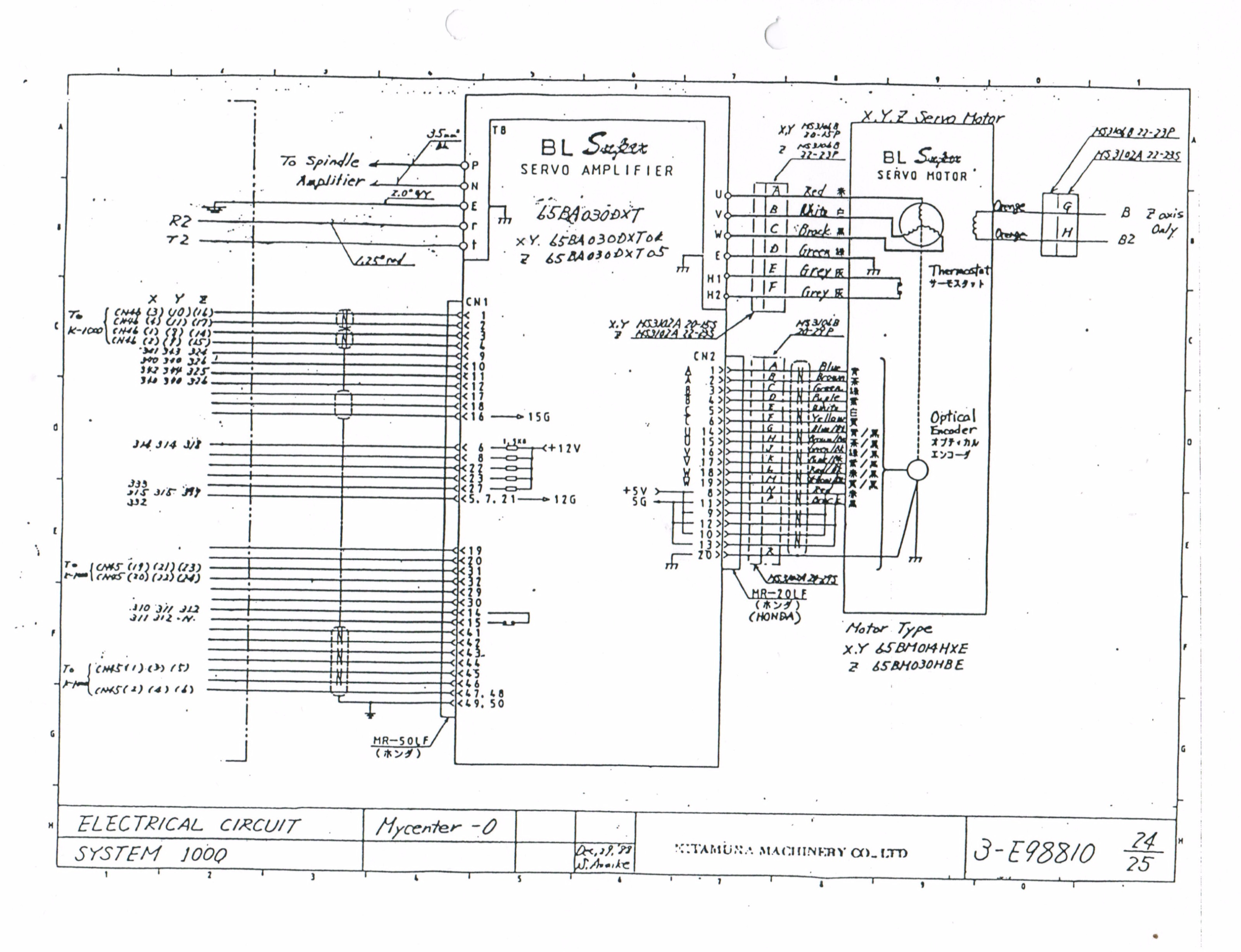
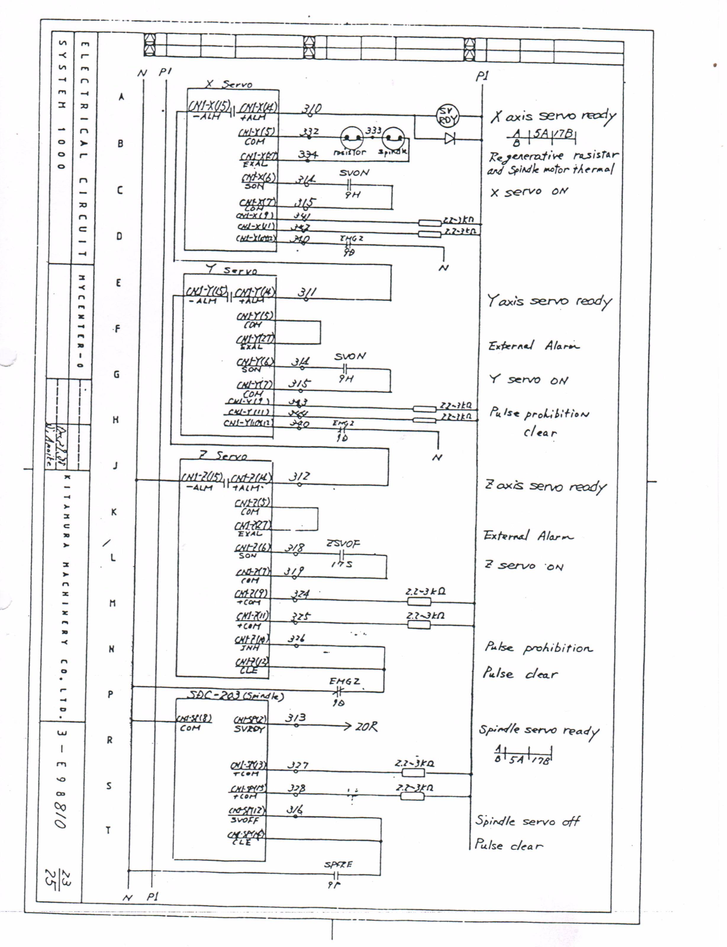
I can not locate a manual for the DA converter (sdc-203) or the Servo amp (20BA150) Here is a link to the machine manual.
olivent.org/wp-content/uploads/2017/07/K...nter-Zero-Manual.pdf
The wiring information starts in appendix 2.
I have attached images of the main sheets that pertain to the spindle. Please ignore the handwritten notes, that is just me attempting to figure out the connections.
I have attached images of the main sheets that pertain to the spindle. Please ignore the handwritten notes, that is just me attempting to figure out the connections.
Please Log in or Create an account to join the conversation.
- Rescue35
-
Topic Author
- Offline
- New Member
-
Less
More
- Posts: 14
- Thank you received: 2
23 Jul 2017 23:04 - 23 Jul 2017 23:12 #96324
by Rescue35
Replied by Rescue35 on topic Kitamura Mycenter Zero Retrofit w/ Mesa 7I92M 7I77
Could it be possible I should be using a 7i76 instead? I've been trying to wrap my head around the axis servos and found this thread.
forum.linuxcnc.org/10-advanced-configura...esa-5i25-7i76-config
It appears my x and y drive are position controlled. The wiring matches the position controlled type as illustrated by the 3rd attachment

It appears my x and y drive are position controlled. The wiring matches the position controlled type as illustrated by the 3rd attachment
Last edit: 23 Jul 2017 23:12 by Rescue35. Reason: resize attachments
Please Log in or Create an account to join the conversation.
- RotarySMP
-

- Offline
- Platinum Member
-
Less
More
- Posts: 1633
- Thank you received: 595
24 Jul 2017 06:06 #96337
by RotarySMP
Replied by RotarySMP on topic Kitamura Mycenter Zero Retrofit w/ Mesa 7I92M 7I77
In the last photo, "Negative command pulse" on CN1- 1&2 and " positive command pulse" on CN1- 3&4 sounds like a digital input of stepping LH or RH, similar to the more common Step/Dir inputs for many stepper drivers. It doesn't sound like the +/-10VDC analog input of velocity controlled servos.
Mark
Mark
Please Log in or Create an account to join the conversation.
- ihavenofish
- Offline
- Platinum Member
-
Less
More
- Posts: 1028
- Thank you received: 286
26 Jul 2017 19:59 #96507
by ihavenofish
Replied by ihavenofish on topic Kitamura Mycenter Zero Retrofit w/ Mesa 7I92M 7I77
those drives may be proprietary serial. many of the sanyos are, but i think, maybe torque control?
the model name gives some clues - the T usually means torque . C is brothers proprietary serial.
these are the modes from the slightly later PY series.
S…Speed control type. T…Torque control type. P…Position control type.
X…S-T switch type Y…P-T switch type U…P-S switch type V…Internal Speed control type
of course, the "pulse" pins on the diagram suggest, not torque control... unfortunately their naming convention isnt very consistent model to model so it may be something else entirely.
Please Log in or Create an account to join the conversation.
- Rescue35
-
Topic Author
- Offline
- New Member
-
Less
More
- Posts: 14
- Thank you received: 2
17 Aug 2017 20:25 #97670
by Rescue35
Replied by Rescue35 on topic Kitamura Mycenter Zero Retrofit w/ Mesa 7I92M 7I77
Thanks for all the help. I'm tired of trying the hard way. I'm replacing all of the electronics so I know that everything works together.
Please Log in or Create an account to join the conversation.
Time to create page: 0.391 seconds