Backlash compensation - strange behaviour on circular shapes
- gimpo
-
 Topic Author
- Offline
- New Member
-

Less
More
- Posts: 8
- Thank you received: 0
24 Dec 2018 18:09 - 24 Dec 2018 18:30 #122830
by gimpo
Backlash compensation - strange behaviour on circular shapes was created by gimpo
Hello,
I'm using the previous version of LinuxCNC (version 2.6.x IIRC) with satisfaction, but few days ago I have registered strange results when milling some test shapes on MDF wood material.
My small portal-router has developed a backlash of 0,2 mm on X and Y axis both, because of wearing. So I gave the backlash-compensation mechanism of LinuxCNC a chance.
After consulting the documentation, I have added the compensation option to my configuration file.
Results was amazing, all my square/rectangular shapes returned to be perfect! I have registered an error around 0.005 mm or less. Wow!
Now the bad news...
My tests on circular pockets shows that all of the internal diameters are around 0,2 mm bigger than what expected. This is exactly the amount of backlash compensation that I'have introduced.
What's going on? I'm missing something?
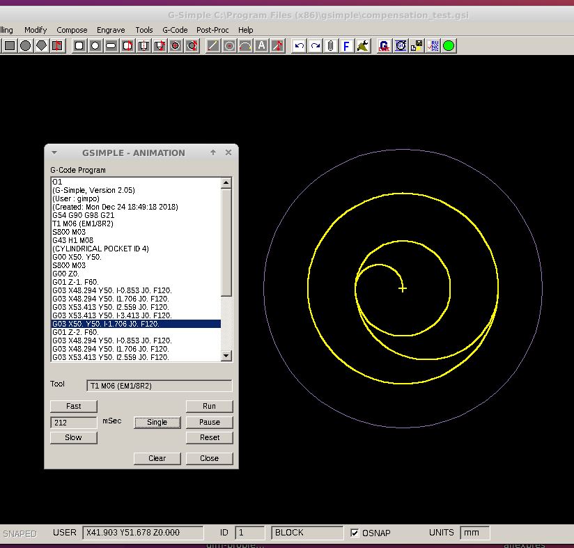
To cut a cylindrical pocket, my software produce a spiral-like path, cutting from the center and then moving outward by using arcs (see below - 12 mm pocket-diameter and 1/8" cutting mill).
Maybe this type of movement somehow influences the effectiveness of the backlash compensation mechanism?

I'm using the previous version of LinuxCNC (version 2.6.x IIRC) with satisfaction, but few days ago I have registered strange results when milling some test shapes on MDF wood material.
My small portal-router has developed a backlash of 0,2 mm on X and Y axis both, because of wearing. So I gave the backlash-compensation mechanism of LinuxCNC a chance.
After consulting the documentation, I have added the compensation option to my configuration file.
Results was amazing, all my square/rectangular shapes returned to be perfect! I have registered an error around 0.005 mm or less. Wow!
Now the bad news...
My tests on circular pockets shows that all of the internal diameters are around 0,2 mm bigger than what expected. This is exactly the amount of backlash compensation that I'have introduced.
What's going on? I'm missing something?
To cut a cylindrical pocket, my software produce a spiral-like path, cutting from the center and then moving outward by using arcs (see below - 12 mm pocket-diameter and 1/8" cutting mill).
Maybe this type of movement somehow influences the effectiveness of the backlash compensation mechanism?
Last edit: 24 Dec 2018 18:30 by gimpo.
Please Log in or Create an account to join the conversation.
- Todd Zuercher
-

- Away
- Platinum Member
-

Less
More
- Posts: 4753
- Thank you received: 1458
24 Dec 2018 19:04 #122834
by Todd Zuercher
Replied by Todd Zuercher on topic Backlash compensation - strange behaviour on circular shapes
You could try using conventional milling instead of climb milling (reverse direction. )
That may change the direction of the cutting forces and hopefully reduce the effect of your backlash.
Unfortunately I don't think the cnc can know the difference if you're doing a female climb milling cut or a male conventional cut. For this reason it is best to eliminate or at least minimize backlash mechanically if possible.
I don’t use backlash comp on our wood routers because for us and the kind of routing we do it usually causes more problems than it solves.
Please Log in or Create an account to join the conversation.
- gimpo
-
Topic Author
- Offline
- New Member
-
Less
More
- Posts: 8
- Thank you received: 0
24 Dec 2018 23:30 #122847
by gimpo
Replied by gimpo on topic Backlash compensation - strange behaviour on circular shapes
Hallo,
I will try your suggestion, but I don't know if the simple CAM program (g-simple) support this option (I love it, it is primitive but I get my basic stuff done in few minutes).
Yesterday I have received new bronze spindle-nuts. Hopefully, with that, I will reduce the backlash below 0,1 mm (finger crossed!).
I'm going to accommodate a TFT display behind a POM/Delrin frame. The frame is perfectly copying the display shape.
It would be fantastic if I could perfectly center the display (the human eye is a perfect machine for catching misalignments). So I'would like to use the compensation for reducing the backlash to around half-tenth of mm (0,05 mm).
Maybe I'm asking too much, but results with circular shapes have confused me...
Please Log in or Create an account to join the conversation.
- gimpo
-
Topic Author
- Offline
- New Member
-
Less
More
- Posts: 8
- Thank you received: 0
26 Dec 2018 19:59 #122922
by gimpo
Replied by gimpo on topic Backlash compensation - strange behaviour on circular shapes
Doubt:
maybe LinuxCNC simply does not support backlash compensation on G02/G03 instructions?
As I understand, applying compensation on a straightforward movement is relatively "easy", but doing the same on an arc-trajectory can quickly turn in a nightmare...
maybe LinuxCNC simply does not support backlash compensation on G02/G03 instructions?
As I understand, applying compensation on a straightforward movement is relatively "easy", but doing the same on an arc-trajectory can quickly turn in a nightmare...
Please Log in or Create an account to join the conversation.
- GeneRF
- Offline
- New Member
-
Less
More
- Posts: 14
- Thank you received: 0
26 Dec 2018 22:54 #122934
by GeneRF
Replied by GeneRF on topic Backlash compensation - strange behaviour on circular shapes
I believe the backlash compensation is very simple. If an axis is moving in a positive direction, no matter how slowly or how small the motion there is no compensation.
If an axis is moving in a negative direction, no matter how slowly or how small the motion there is the full specified compensation.
There is no ramping or blending for curves. Backlash compensation is either fully applied or not applied. It is independent for each axis.
Gene
If an axis is moving in a negative direction, no matter how slowly or how small the motion there is the full specified compensation.
There is no ramping or blending for curves. Backlash compensation is either fully applied or not applied. It is independent for each axis.
Gene
Please Log in or Create an account to join the conversation.
- gimpo
-
Topic Author
- Offline
- New Member
-
Less
More
- Posts: 8
- Thank you received: 0
27 Dec 2018 21:32 #122972
by gimpo
Replied by gimpo on topic Backlash compensation - strange behaviour on circular shapes
For the arcs is not that simple. Take a piece of paper and a pencil and make some tests.
While for linear movements the compensation turns simply in a longer segment (even for segments not parallel to the X or Y axis), for arcs you can encounter the situation where there is zero backlash in the Y direction, but non-zero backlash in the Y direction, or vice-versa.
The resulting path is no more an arc, but a very strange curve, difficult to draw by using g-code instructions (i.e. a linear transformation along one axis).
Please Log in or Create an account to join the conversation.
- Todd Zuercher
-
- Away
- Platinum Member
-
Less
More
- Posts: 4753
- Thank you received: 1458
27 Dec 2018 22:06 #122975
by Todd Zuercher
Replied by Todd Zuercher on topic Backlash compensation - strange behaviour on circular shapes
Backlash compensation's implementation is simpler than you think (you're over thinking it)
It is merely an additional movement added to the beginning of the 1st move after any direction reversal. no more no less. It is made at the fastest speed possible (limited by the stepgen's max velocity and acceleration. How quickly it may be taken up will depend on the headroom given between those max speeds and the commanded feed rate of the move. Once the move is applied all movement is as commanded until the next direction reversal of that axis.
So for milling a circle, there will only be at the most 4 backlash compensating moves one for each of the two X and Y reversals. If everything is perfect you get a smooth circle, but usually you will end up with a small imperfection at each of the 4 reversal points. If you have used too much backlash compensation you will actually get a little step inward at each of the reversal points. If you arn't using enough backlash comp, the effect is difficult do describe, sort of a flat spot and slight distortion of the arc, and isn't as noticeable.
The bigger problem is that cutting forces can work against you taking up the backlash without or before the backlash move, resulting in an obvious step when the backlash move is made resulting in all sorts of ugliness.
Please Log in or Create an account to join the conversation.
- gimpo
-
Topic Author
- Offline
- New Member
-
Less
More
- Posts: 8
- Thank you received: 0
27 Dec 2018 22:41 - 27 Dec 2018 22:50 #122981
by gimpo
Replied by gimpo on topic Backlash compensation - strange behaviour on circular shapes
Maybe you're right, it sounds reasonable.
But... how can this explain my almost perfect 10 mm cylindrical-pockets* without compensation**, versus my buggy 10.2 mm pockets with compensation active, on a soft material, like the MDF is?
As you pointed out, the micro-steps at reversal points should be directed inward, not outward. The resulting shape, in the worst case, should result ugly but smaller, not bigger. I'm missing something?
(*) In one case I have registered 10.00 mm, that is the max precision of my caliper.
(**) 0.2 mm of compensation applied on Y and X axis both .
Last edit: 27 Dec 2018 22:50 by gimpo.
Please Log in or Create an account to join the conversation.
- Todd Zuercher
-
- Away
- Platinum Member
-
Less
More
- Posts: 4753
- Thank you received: 1458
28 Dec 2018 04:30 #123001
by Todd Zuercher
Replied by Todd Zuercher on topic Backlash compensation - strange behaviour on circular shapes
What size tool were you using? Describe your machine and spindle?
Please Log in or Create an account to join the conversation.
Time to create page: 0.139 seconds