Biesse Rover 322 MESA retrofit
- tom_no
-
 Topic Author
- Offline
- Junior Member
-

Less
More
- Posts: 31
- Thank you received: 7
15 Sep 2020 21:44 #182285
by tom_no
Replied by tom_no on topic Biesse Rover 322 MESA retrofit
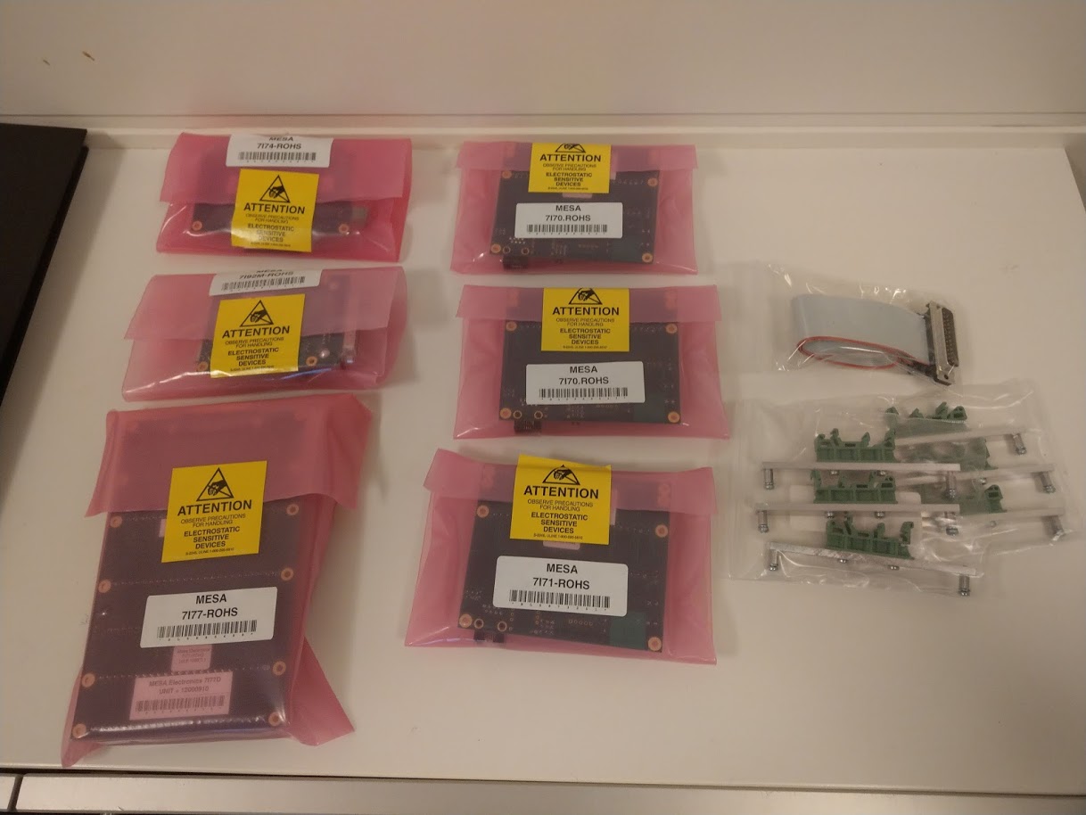
Today I've received the (first) shipment of MESA cards and started fiddling with a Laptop for testing. Got LinuxCNC 2.8.0 Debian 10 Buster installed and after some hassle got it to talk to the 7i92. Uploaded the firmware config for 7i92 + 7i77 + 7i44 through the terminal window.
If anyone reading here has the ability to give input to whomever compiles the packages for the ISO it would be nice if the WIKD Network Manager was replaced with the Gnome one - as the former does not have the functionality needed to configure a connection to the MESA 7i92.
Question: How do I add firmwares for card combinations to PNCCONF? There are only 6 combinations available in the drop-down list in the wizard, and I'd like to add the 7i77+7i44 one I'm using.
Looks like I need to add a 7i71 and a 7i83 to gain control over all IO's.
Please Log in or Create an account to join the conversation.
- tommylight
-

- Away
- Moderator
-

Less
More
- Posts: 21712
- Thank you received: 7418
15 Sep 2020 22:28 #182292
by tommylight
 You have a 7i74, and there is no need for that, i did all that manually. The 7i74 is transparent so all you really see is the 7i70 and 7i71 connected to it.
You can also use pncconf to create the I/O pins for 7i77 then open the hal file and cut the I/O stuff and paste to a new text file, use "find and replace" feature on all Linux text editors to replace the 7i77.0.n with the relevant 7i70.n.n or 7i71.n.n, then paste them back to the main hal file. Or make a new hal file for the 7i70 and 7i71 as i did, add it to the ini file, and use the procedure above just to cut and paste and replace.
It might seem complicated, but it really is not, just give it a try and do not worry if it does not work, you can make as many configs as you like, and that is also a good advice, make a simple config and test, if it works make a copy of it and add more stuff then test then again copy and add more stuff, and so on. Saves a lot of time and nerves if something goes wrong as you can always make a copy of the last known good config and continue without having to start from scratch.
Replied by tommylight on topic Biesse Rover 322 MESA retrofit
Question: How do I add firmwares for card combinations to PNCCONF? There are only 6 combinations available in the drop-down list in the wizard, and I'd like to add the 7i77+7i44 one I'm using.
You have a 7i74, and there is no need for that, i did all that manually. The 7i74 is transparent so all you really see is the 7i70 and 7i71 connected to it.You can also use pncconf to create the I/O pins for 7i77 then open the hal file and cut the I/O stuff and paste to a new text file, use "find and replace" feature on all Linux text editors to replace the 7i77.0.n with the relevant 7i70.n.n or 7i71.n.n, then paste them back to the main hal file. Or make a new hal file for the 7i70 and 7i71 as i did, add it to the ini file, and use the procedure above just to cut and paste and replace.
It might seem complicated, but it really is not, just give it a try and do not worry if it does not work, you can make as many configs as you like, and that is also a good advice, make a simple config and test, if it works make a copy of it and add more stuff then test then again copy and add more stuff, and so on. Saves a lot of time and nerves if something goes wrong as you can always make a copy of the last known good config and continue without having to start from scratch.
Please Log in or Create an account to join the conversation.
- tommylight
-
- Away
- Moderator
-
Less
More
- Posts: 21712
- Thank you received: 7418
15 Sep 2020 22:58 #182296
by tommylight
")
Replied by tommylight on topic Biesse Rover 322 MESA retrofit
The right side drive is on positive limit !
Please Log in or Create an account to join the conversation.
- tom_no
-
Topic Author
- Offline
- Junior Member
-
Less
More
- Posts: 31
- Thank you received: 7
16 Sep 2020 13:05 #182434
by tom_no
Replied by tom_no on topic Biesse Rover 322 MESA retrofit
The right side drive is on positive limit !
Hehe, yes you are right. I believe it's for the Z-axis. Think I read Bevins or someone else had the same issue when retrofitting another Biesse, because of missing compressed air to the lift cylinder/air suspension. Hope to get it out of limit when connecting air this weekend. Good to have the confirmation though - could have been "anything".
The following user(s) said Thank You: tommylight
Please Log in or Create an account to join the conversation.
- tom_no
-
Topic Author
- Offline
- Junior Member
-
Less
More
- Posts: 31
- Thank you received: 7
16 Sep 2020 13:30 #182437
by tom_no
Thanks! 7i74 being transparent makes sense. Copying and pasting between configs should be straight forward when I get the basics and overview, but I feel I'm at least half a step behind in the configuring, missing out on some basics. Is there a way to test the connection to the connection to the serial connected boards before going to HAL? Or do they need to be activated in HAL to go online? I think I read something about the lights not changing to green until triggered in HAL?
This is my test setup so far:
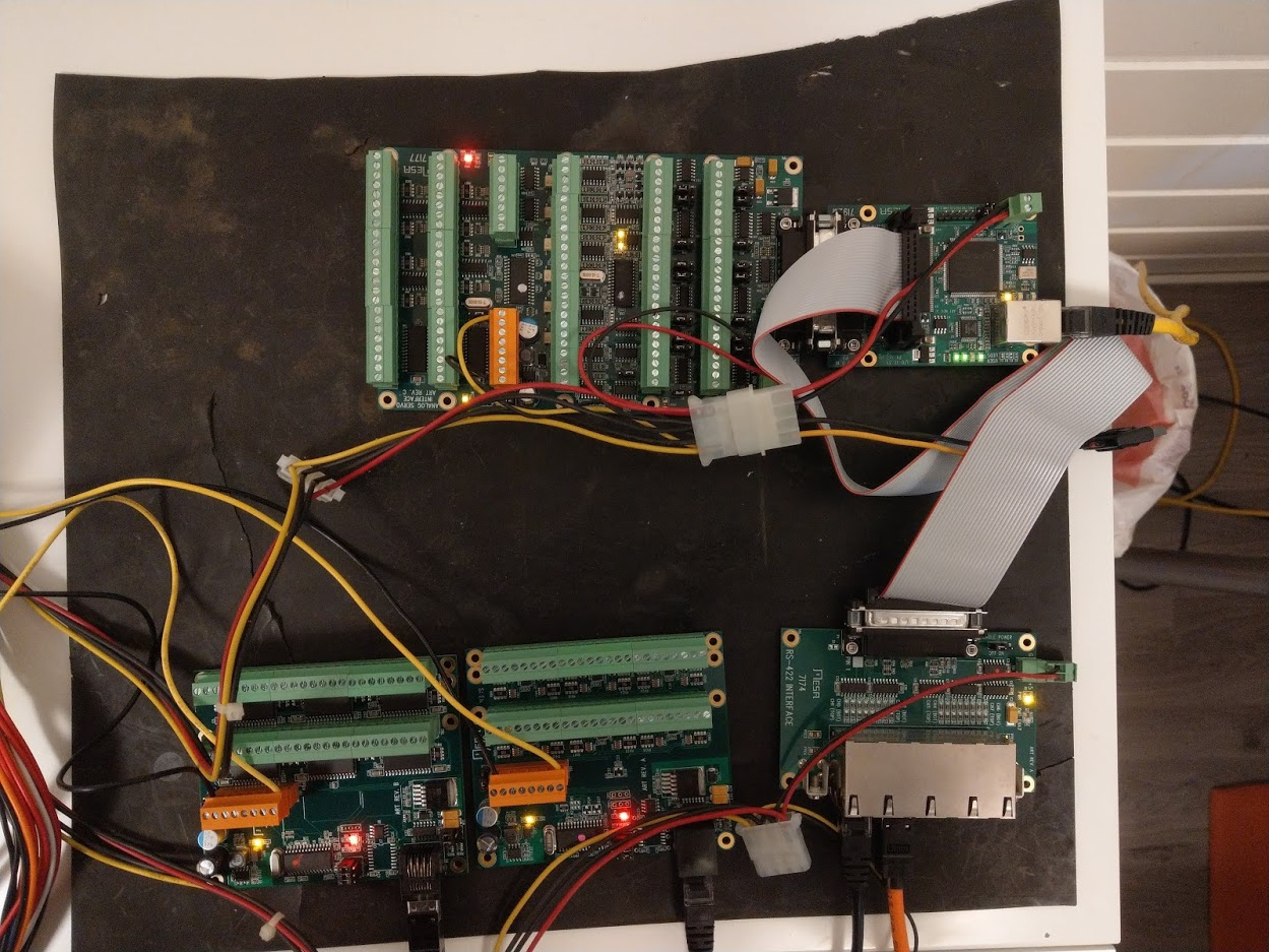
I think my current goal should be to get control over IO's at the 7i70, 7i71 and 7i77 cards (servos, resolvers etc will have to wait until I install in the machine). IE see if inputs are false/true and control the outputs.
I also foresee an issue on nomenclature; LinuxCNC has a lot of predefined names for different pins, while my schematic may have other names. Can I use both? As in using a software link between LinuxCNC name and Biesse Name and use the Biesse name on the actual pin? Would that make sense at all?
Replied by tom_no on topic Biesse Rover 322 MESA retrofit
Question: How do I add firmwares for card combinations to PNCCONF? There are only 6 combinations available in the drop-down list in the wizard, and I'd like to add the 7i77+7i44 one I'm using.
You can also use pncconf to create the I/O pins for 7i77 then open the hal file and cut the I/O stuff and paste to a new text file, use "find and replace" feature on all Linux text editors to replace the 7i77.0.n with the relevant 7i70.n.n or 7i71.n.n, then paste them back to the main hal file. Or make a new hal file for the 7i70 and 7i71 as i did, add it to the ini file, and use the procedure above just to cut and paste and replace.
It might seem complicated, but it really is not, just give it a try and do not worry if it does not work, you can make as many configs as you like, and that is also a good advice, make a simple config and test, if it works make a copy of it and add more stuff then test then again copy and add more stuff, and so on. Saves a lot of time and nerves if something goes wrong as you can always make a copy of the last known good config and continue without having to start from scratch.
Thanks! 7i74 being transparent makes sense. Copying and pasting between configs should be straight forward when I get the basics and overview, but I feel I'm at least half a step behind in the configuring, missing out on some basics. Is there a way to test the connection to the connection to the serial connected boards before going to HAL? Or do they need to be activated in HAL to go online? I think I read something about the lights not changing to green until triggered in HAL?
This is my test setup so far:
I think my current goal should be to get control over IO's at the 7i70, 7i71 and 7i77 cards (servos, resolvers etc will have to wait until I install in the machine). IE see if inputs are false/true and control the outputs.
I also foresee an issue on nomenclature; LinuxCNC has a lot of predefined names for different pins, while my schematic may have other names. Can I use both? As in using a software link between LinuxCNC name and Biesse Name and use the Biesse name on the actual pin? Would that make sense at all?
Please Log in or Create an account to join the conversation.
- tommylight
-
- Away
- Moderator
-
Less
More
- Posts: 21712
- Thank you received: 7418
16 Sep 2020 14:39 #182440
by tommylight
Replied by tommylight on topic Biesse Rover 322 MESA retrofit
There is a way of showing all the pins or parameters or whatever needed suing the terminal, but i use a more unconventional way by making a rough config for the 7i92/7i77 and running LinuxCNC, then from the "machine" menu select the "show hal configuration" and there look for pins on the 7i77 or 7i70 or 7i71 or any other SSerial card. On that window there is a tab named "show" so you can choose the pins and watch them change state.
Please Log in or Create an account to join the conversation.
- tom_no
-
Topic Author
- Offline
- Junior Member
-
Less
More
- Posts: 31
- Thank you received: 7
23 Sep 2020 00:14 #183360
by tom_no
Replied by tom_no on topic Biesse Rover 322 MESA retrofit
Currently working on two fronts. Got the MESA cards running with HAL configuration and all pins visible in LCNC. Next up here is figuring out the basics/framework for the HAL and INI files. Are there any suitable example files out there for inspiration?
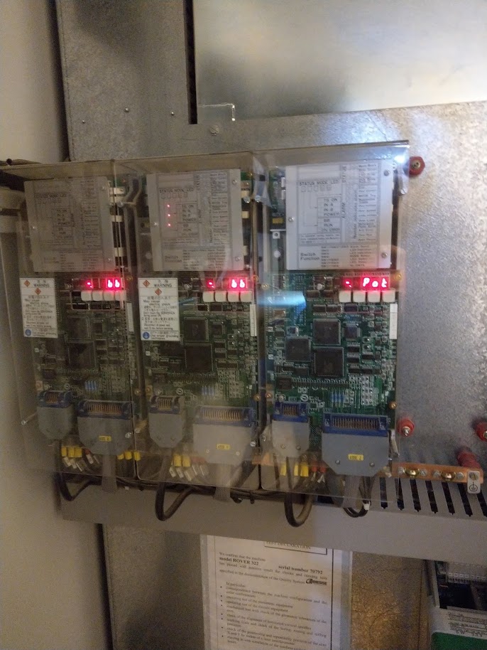
On the eastern front I'm still working to get the existing XNC system running. I'd very much like to jog all axis and start some spindles etc to test and verify as much as possible before shutting down and disconnecting XNC permanently. Got the big safety loop ironed out (PLC 9001 fault) and the machine starting. Also got the safety mats connected and green lighted. But still got 9004 Emergency stop from inverter and 9038, 9039, 9040 Activation of Axes 1-3 to deal with.
All servo drives now show "bb" Base Block - which I guess is normal until activated from sofrware via IO?
The inverter shows "rdy" in the display so I'm a bit bummed out as to the 9004 Emergency stop from inverter fault. Is it actually from the inverter, or is there more going on behind the scenes as with the PLC 9001 fault?
It would be really helpful to know the normal start-up procedure for the system - does the first power-up for the day always involve some form of software reset before homing, then warmup? Am I dealing with lack of software knowledge or a electrical issue?
Please Log in or Create an account to join the conversation.
- tom_no
-
Topic Author
- Offline
- Junior Member
-
Less
More
- Posts: 31
- Thank you received: 7
28 Sep 2020 17:22 #184184
by tom_no
Replied by tom_no on topic Biesse Rover 322 MESA retrofit
A quick progress update:
Eventually abandoned getting the old CNI XNC system up and running. I believe I got the safety systems/loops figured out and retrieved some useful information regarding machine settings before powering it down, but never got the axis moving. At one point I figured I had run out of ideas and the old PLC/PC was getting unstable and it was time to move on.
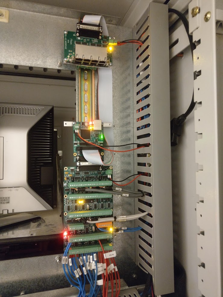
Exit CNI XNC and enter MESA+LCNC. I've removed the old computer and IO modules from the switchboard and rewired most to the MESA 7i77 board. Got to a nice milestone last night where the encoders are working and calibrated to show accurate values in the DRO. Must say that 3.4 meters of X-travel is quite substantial.
If someone else down the line should be contemplating a similar retrofit here is a few notes I would have found helpful to know before setting out:
*The CNI XNC PLS system is comprised of a PC running Lynx Unix with internal boards for servo control and nine external IO modules.
* There are two IO modules inside the switchboard with about 20 inputs and nine output relays. This is mainly related to safetyloops and controlling the power switches, servos and VFD. The 7i77 has plenty of connections to run all of what's going on in the switchboard, but I got myself 10 DIN rail external relays for the outputs as they have a variety of voltages and currents.
* There are three IO modules inside the "head" of the machine - IE on top of the Y-axis. There are about 24 inputs and 45 outputs, mainly controlling pneumatic solenoids for the drilling and main spindles. I will use a 7i70 and a 7i71 to replace these modules, giving me just a couple of spare outputs, but plenty of inputs. The solenoids draw 5.05 watts at 24 volts and have flyback (?) diodes, which should be comfortably within the range of the 7i71. Hopefully I will not get any surprises with bigger ones as I dig further into the machine...
* There are two IO modules in the left side base of the machine, mainly running the toolchanger. There are about 17 inputs and 12 outputs. I will probably need another 15+10 IO's if santa brings me a second rack for the toolchanger. I plan to run a 7i70+7i71 combo here as well, but could maybe get away with a 7i84 if I stick to 5 holders only.
* There are two IO modules in the center of the base of the machine, mainly running the suction and posts on the pallets. There are about 8 inputs and 16 outputs. I plan to get a MESA 7i84 to run these.
* Error messages in the CNI XNC system are not very precise and may involve a lot more than one may think at first glance. Example is the "thermal switch" that indicate issue with the power switches, but actually is a long safetyloop giving power to a safety relay needed to power the machine up (thermal switches, air pressure, e-stop trip wire, door in fence closed etc). Similar with the vacuum indicator - also a safetyloop containing more than meets the eye.
Next on my list is to get the servo drives activated and then to tune the servos and home the machine. Then probably replace the rest of the IO modules and start some serious HAL programming to get the machine usable and safe.
Pictures or it did not happen:

Eventually abandoned getting the old CNI XNC system up and running. I believe I got the safety systems/loops figured out and retrieved some useful information regarding machine settings before powering it down, but never got the axis moving. At one point I figured I had run out of ideas and the old PLC/PC was getting unstable and it was time to move on.
Exit CNI XNC and enter MESA+LCNC. I've removed the old computer and IO modules from the switchboard and rewired most to the MESA 7i77 board. Got to a nice milestone last night where the encoders are working and calibrated to show accurate values in the DRO. Must say that 3.4 meters of X-travel is quite substantial.
If someone else down the line should be contemplating a similar retrofit here is a few notes I would have found helpful to know before setting out:
*The CNI XNC PLS system is comprised of a PC running Lynx Unix with internal boards for servo control and nine external IO modules.
* There are two IO modules inside the switchboard with about 20 inputs and nine output relays. This is mainly related to safetyloops and controlling the power switches, servos and VFD. The 7i77 has plenty of connections to run all of what's going on in the switchboard, but I got myself 10 DIN rail external relays for the outputs as they have a variety of voltages and currents.
* There are three IO modules inside the "head" of the machine - IE on top of the Y-axis. There are about 24 inputs and 45 outputs, mainly controlling pneumatic solenoids for the drilling and main spindles. I will use a 7i70 and a 7i71 to replace these modules, giving me just a couple of spare outputs, but plenty of inputs. The solenoids draw 5.05 watts at 24 volts and have flyback (?) diodes, which should be comfortably within the range of the 7i71. Hopefully I will not get any surprises with bigger ones as I dig further into the machine...
* There are two IO modules in the left side base of the machine, mainly running the toolchanger. There are about 17 inputs and 12 outputs. I will probably need another 15+10 IO's if santa brings me a second rack for the toolchanger. I plan to run a 7i70+7i71 combo here as well, but could maybe get away with a 7i84 if I stick to 5 holders only.
* There are two IO modules in the center of the base of the machine, mainly running the suction and posts on the pallets. There are about 8 inputs and 16 outputs. I plan to get a MESA 7i84 to run these.
* Error messages in the CNI XNC system are not very precise and may involve a lot more than one may think at first glance. Example is the "thermal switch" that indicate issue with the power switches, but actually is a long safetyloop giving power to a safety relay needed to power the machine up (thermal switches, air pressure, e-stop trip wire, door in fence closed etc). Similar with the vacuum indicator - also a safetyloop containing more than meets the eye.
Next on my list is to get the servo drives activated and then to tune the servos and home the machine. Then probably replace the rest of the IO modules and start some serious HAL programming to get the machine usable and safe.
Pictures or it did not happen:
The following user(s) said Thank You: tommylight, Masiwood123
Please Log in or Create an account to join the conversation.
- tom_no
-
Topic Author
- Offline
- Junior Member
-
Less
More
- Posts: 31
- Thank you received: 7
03 Oct 2020 20:53 #184726
by tom_no
Replied by tom_no on topic Biesse Rover 322 MESA retrofit
Got some good progress this week, getting drives activated and somewhat running. Encoder scales and directions plus homing seems to work perfectly. However, I'm struggling bigtime with the servo tuning. I have found settings that allow jogging up to a certain speed, but get "not following error" when increasing speed. I suspect I've arrived at Calibration values that "work", but probably are far from sane.
Need help pointing out where I've taken the wrong turn and how to get back on the right track.
I think my Output scale is way off, but if I bring it down to 10 as suggested in the guide the machine literally jumps (all 3.7 tons of it). It tries to move quite violently and immediately shuts down (faults out in LCNC). I've attached my HAL and INI files for reference.
Any and all suggestions will be greatly appreciated.
Please Log in or Create an account to join the conversation.
- PCW
-

- Offline
- Moderator
-
Less
More
- Posts: 17971
- Thank you received: 5272
03 Oct 2020 21:53 #184737
by PCW
Replied by PCW on topic Biesse Rover 322 MESA retrofit
A couple of things
if you have an output scale of 150 the limits must be +- this number:
OUTPUT_SCALE = 150
OUTPUT_MIN_LIMIT = -150
OUTPUT_MAX_LIMIT = 150
2. If these are velocity mode drives, most of the tuning will be done with FF1
Further, if you have OUTPUT_SCALE set correctly (the velocity at 10V)
FF1 == 1.000
if you have an output scale of 150 the limits must be +- this number:
OUTPUT_SCALE = 150
OUTPUT_MIN_LIMIT = -150
OUTPUT_MAX_LIMIT = 150
2. If these are velocity mode drives, most of the tuning will be done with FF1
Further, if you have OUTPUT_SCALE set correctly (the velocity at 10V)
FF1 == 1.000
Please Log in or Create an account to join the conversation.
Time to create page: 0.224 seconds