Retrofit of a Hitachi-Seike VK45 mill
- ZincBoy
- Offline
- Junior Member
-

Less
More
- Posts: 34
- Thank you received: 15
09 Mar 2021 23:12 #201613
by ZincBoy
Replied by ZincBoy on topic Retrofit of a Hitachi-Seike VK45 mill
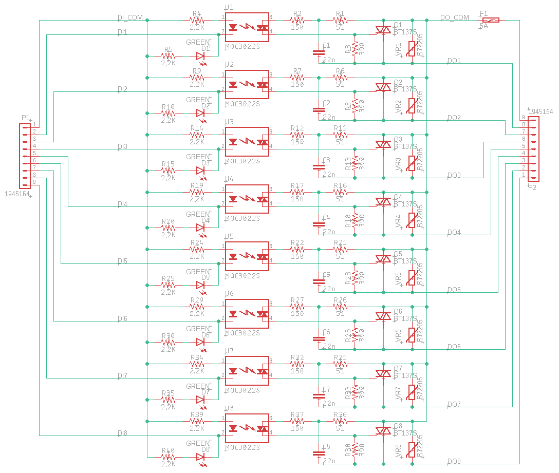
The SSR board is something I came up with the drive the solenoids and contactor coils in the mill. The factory control had SSR boards but they were half burnt out and the SSRs were $50 each. I could have used lower cost off the shelf SSRs but they are still quite expensive, large, and I would need to create a board anyway. Total cost to build 6 SSR boards was about $100 and they fit the areas I needed them to.
Each board has 8 channels of optically isolated 100-240V switching. The triacs used are rated for 8A but there is virtually no heatsinking so the board is only good for about 1A/channel and 5A/board. Over sizing the triacs was done to hopefully avoid the burn out issue the factory ones suffered from. The factory SSRs were rated at 1A.
As can be seen from the schematic, the circuit is very simple. D1-8 are indicator LEDs that show when a channel is active. U1-8 are optically isolated triacs. The R1,2,3,C1 network helps make sure the power triac Q1 turns off. VR1-8 are MOVs that absorb any transients created by switching the inductive loads. The fuse F1 protects the high voltage outputs from overload. The factory fuses had open indicators that were fed back to the PLC but I will rely on things just not working
Some notes:
- This is not a zero cross switching design. It should be possible to make it zero cross by replacing U1-8 with appropriate isolators.
- C1-8 are high voltage capacitors and should be rated to see line voltage. This makes this one of the more expensive parts of the design
- 1206 size resistors should be used or care should be taken to make sure the voltage ratings are not exceeded.
- VR1-8 voltage rating should be selected to match the line voltage used. Since my system uses 100Vac, I used 115Vac rated MOVs.
Attachments:
The following user(s) said Thank You: J Green
Please Log in or Create an account to join the conversation.
- J Green
- Offline
- Elite Member
-

Less
More
- Posts: 164
- Thank you received: 24
10 Mar 2021 01:54 #201622
by J Green
Replied by J Green on topic Retrofit of a Hitachi-Seike VK45 mill
I like your approach for the SSR Bd , it is easy to check an repair- replace if needed . If the open fuse indicator should become needed then might consider a neon bulb for visual indication .
The factory SSRs were rated at 1A Back when that design was done I bet the SSR speck sheet indicated they were way over what was needed . Your choice of 5 Amp devices should mean they have a bigger junction for heat dissipation an larger surge capacity .
Thank You again for sharing
Bob
The factory SSRs were rated at 1A Back when that design was done I bet the SSR speck sheet indicated they were way over what was needed . Your choice of 5 Amp devices should mean they have a bigger junction for heat dissipation an larger surge capacity .
Thank You again for sharing
Bob
Please Log in or Create an account to join the conversation.
- ZincBoy
- Offline
- Junior Member
-

Less
More
- Posts: 34
- Thank you received: 15
14 Aug 2021 18:12 #217758
by ZincBoy
Replied by ZincBoy on topic Retrofit of a Hitachi-Seike VK45 mill
Updated configuration files for the mill are attached. I fixed quite a few bugs over the last few months. As the mill gets used, I keep finding interesting corner cases that need more logic  All part of the fun.
Attachments:
The following user(s) said Thank You: andypugh
Please Log in or Create an account to join the conversation.
Time to create page: 0.082 seconds

