Retrofitting a MAHO MH500W '89-'90 with hand-feed

More
3 years 9 months ago #263252 by tommylight
Do drives have a separate enable for each drive?
If yes,
-leave everything as is
-estop input in Mesa to e-stop-ext in hal
-drive enable to x-enable or machine-is-enabled in hal
-no latch
--
Some things to keep in mind,
-you do not want the machine to cut power to everything because of a joint error or a tripped limit or home switch
-as long as LinuxCNC has full controll of drive enables, the rest is more or less OK.
-you have a physical e-stop, so no need for a software one, in case of need, finding the e-stop on screen and clicking on it takes much longer than pushing a button by palm/hand/foot.
The following user(s) said Thank You: petmakris

Please Log in or Create an account to join the conversation.
More
3 years 9 months ago - 3 years 9 months ago #263259 by petmakris
The driver/amplifier's motor enable is controlled by this /ESTOP line (the one that goes 24V once the machine is powered on via 7K2 and 7K3). So I don't controll the enable of the amplifier from mesa. 

If you check the screenshot, on the left, only the 3x (+/-) 10V analog controls for the motors I have access to. No drive enable is accessible to control from mesa.

If  /ESTOP goes low, the amplifier is deactivated. Another way to deactivate axis, is by 8K1, 9K1, 10K1 for the handwheels, something that I will not bother with for now.  
Last edit: 3 years 9 months ago by petmakris.

Please Log in or Create an account to join the conversation.
More
3 years 9 months ago - 3 years 9 months ago #263262 by petmakris
There are two signals in maho
  1. /ESTOP: this is the external estop (LinuxCNC input)
  2. P_ON: the control of relay K1 (LinuxCNC output)
If I wire the /ESTOP to external estop in mesa, what should I do the second signal?
When should I drive it low (and how)?

The complexity in my mind is that when /ESTOP is low (e.g. before trying to power up the machine) then the second signal should be high so the machine can power up so they don't share the same state. 

 
Last edit: 3 years 9 months ago by petmakris.

Please Log in or Create an account to join the conversation.
More
3 years 5 months ago #271814 by petmakris
Unfortunately, I am having problems tuning my PIDs.

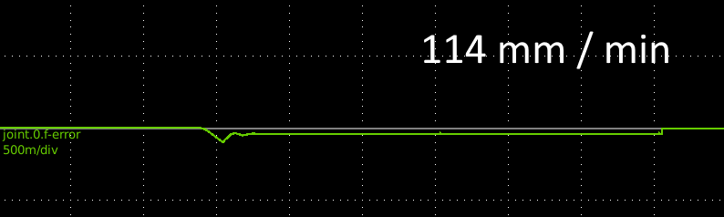
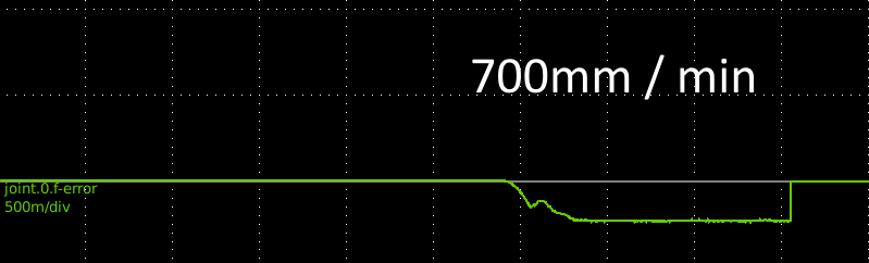
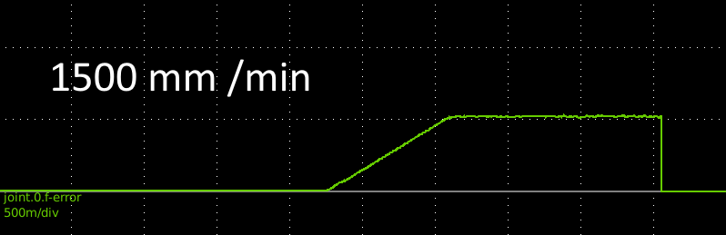
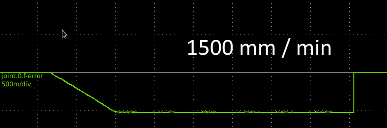
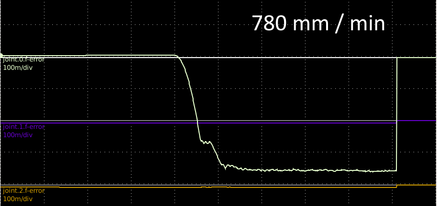
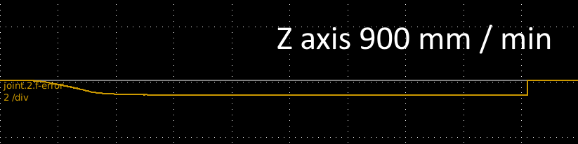
When the machine is moving with constant velocity shouldn't the f-error be close to zero? like in a resting/idle state? In my case the following error is proportional to moving velocity.

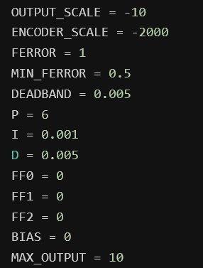
I cannot utilize the I and D terms. I=0, D=0 seems a good value for both and adding any amount bigger than 0.001 to either I or D results in oscillations (different than the oscillations of high P) 

I cannot add either FF1, FF2, FF3, it causes oscillations too. Additionally I don't see why I should add FF0 and FF1, FF2 aren't they related only to the commanded position?

In the pictures, the f-error converges to a non-zero values which is proportional to the moving velocity. 


The only settings that work a bit well but (not quite) are:


The complete configuration is at

X Axis (all axis have similar configs)
github.com/petmakris/maho-mh500w/blob/ma...onfig/inc/axis-x.inc

Complete configuration:
github.com/petmakris/maho-mh500w/tree/main/config


Please Log in or Create an account to join the conversation.
More
3 years 5 months ago #271825 by PCW
If these are velocity mode drives, you must have FF1 for decent performance
Note that if you scale the analog output to the drives machine velocity in
units per second at 10V, FF1=1.0.

If you leave the default scaling of 10 (= scaling in volts), FF1 =
10/drive_velocity_at_10V

Please Log in or Create an account to join the conversation.
More
3 years 5 months ago #271836 by petmakris

If these are velocity mode drives, you must have FF1 for decent performance
Note that if you scale the analog output to the drives machine velocity in
units per second at 10V, FF1=1.0.

If you leave the default scaling of 10 (= scaling in volts), FF1 =
10/drive_velocity_at_10V
 
I suspect that I have a velocity mode amplifier (It's an Indramat 3TRM3) because I have applied constant voltage and it was moving at constant velocity. Can you explain how to tell if it's a velocity or torque driven servo system? I can't find any information anywhere for this.

Another thing, which parameter has a default value of 10? is it the OUTPUT_SCALE from the INI file? because this defaults to 1V.

I just some other post you said

For velocity mode PID use I like to set scalemax to the drives machine units (inches or mm) per second at 10V in. This normalizes the PID loop so FF1 can be set to 1.

Which parameter is this scalemax? Can't find it image missing /media/kunena/emoticons/dizzy.png

Please Log in or Create an account to join the conversation.
Time to create page: 0.132 seconds
Powered by Kunena Forum