- Hardware & Machines
- CNC Machines
- gathering ideas for a tool changer system on my 48" X 48" CNC router table
gathering ideas for a tool changer system on my 48" X 48" CNC router table
- travis036
-
 Topic Author
- Offline
- Elite Member
-

Less
More
- Posts: 283
- Thank you received: 32
09 Jan 2023 16:23 #261363
by travis036
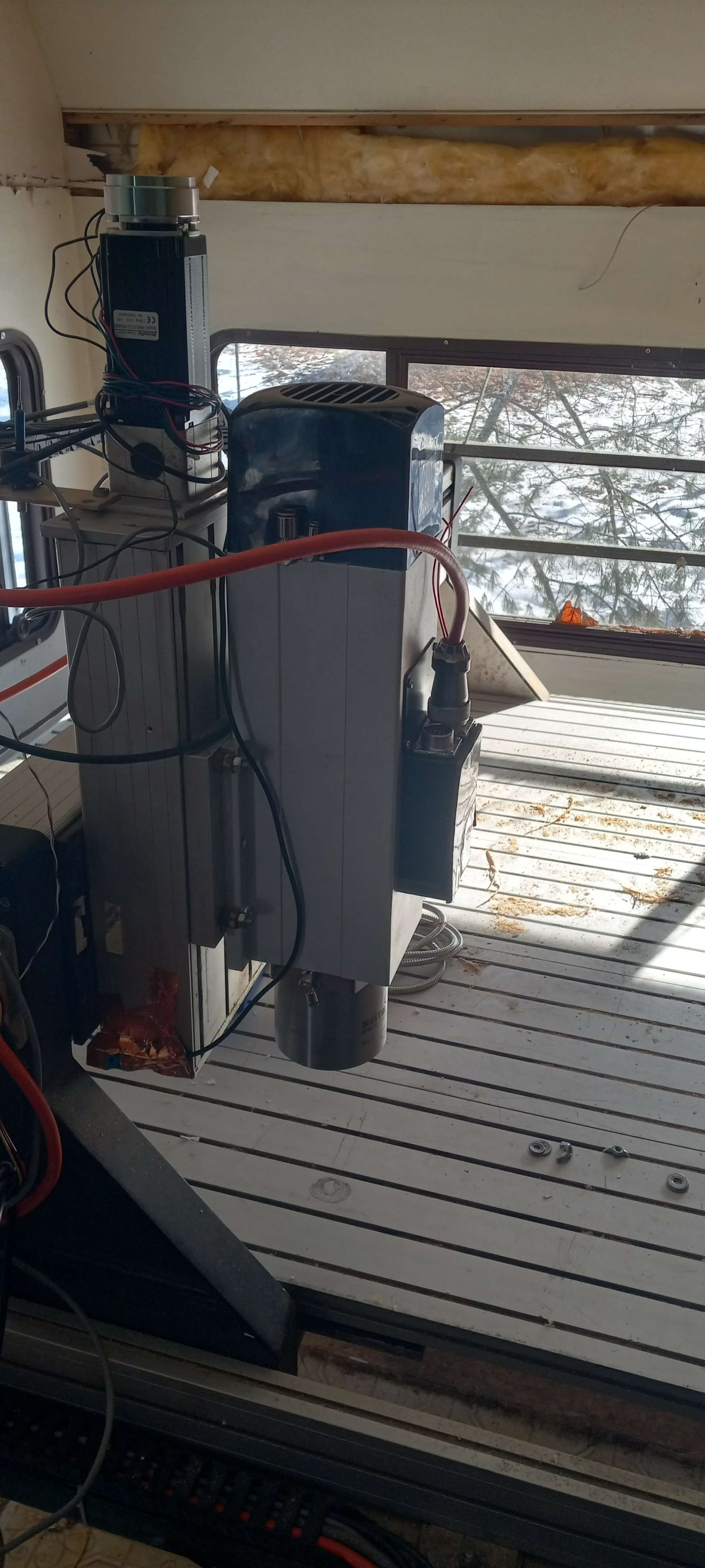
the attached picture is of the ATC spindle mounted on my machine. the mount style may be temporary, or permanent, depending on how well it works. also, the copper tape holding the Z-axis homing sensor on IS temporary, until i make a solid mount.
the whole Z-axis box moves up and down with the spindle, so this presents a clearance issue for a rear tool changer. this is especially true, considering i think the spindle needs to move up more on the Z-box so the attached tools have more clearance over the workpiece (router is for woodworking).
the options as i see them, are either a front tool rack, that would be in the way all the time, a rear rack that the tool holders are lifted out of, so to clear the Z-box, or a front load system, where the tool holder is grabbed from the carousel that is on the front, but off to the side, and has a loading arm that swings around and picks the tool holder, then swings back and loads the tool in the spindle.
personally, i like the front-side carousel, with swing arm idea, though implementing it could be very complicated, and expensive.
for a rough overview of my machine, it can be seen in my YouTube video here:
this is a slightly dated video as it still has the old spindle and VFD on the machine, but should give a rough idea what i am working with.
feel free to suggest other options or ideas, as that is the point of my post here.
i am thinking of using some pockets to suspend the tool holders by the retention knob on top. i could make a sort of fork that slides in place to secure the knob, and is actuated by something like a car door lock actuator. only one is needed, right at the change location.
the swing arm will have a BT30 fork to slide into the ring at the base of the cone. it only needs to move side to side, and up and down to lower the tool holder out of the pocket. once lowered, it swings over to the spindle change location, and then rises up to meet the spindle, where it is locked in place, and the arm swings out of the way.
for the swing arm, i have a pneumatic double-acting cylinder i can use to move it side to side.
so i need a way to move the tool grabber up and down, possibly pneumatic.
the carousel, i would like to be a chain style, so it can take up less space, but could be a round style too. mostly because it is less complicated.
i have 1 stepgen channel left on my 7i80HD-16 configuration (SVST8_4). so that could rotate the carousel. for simplicity, i could have one indexing sensor for homing the "axis", and program in degree stops for each pocket. so it would act like a rotary axis. the trick would be to evenly space the pockets so the machine can find them in the right spot.
for media to build from, i have lots of scrap plywood, that i "think" should be stable enough, with enough sealer on it to keep the humidity from warping it.
anybody think this sounds doable? or am i destined to encounter a massive catastrophic failure? and as i said, further ideas are welcome. keep in mind, i am a woodworker, so the tools i have cut and shape wood, not metal (generally). so i don't have access to a metal mill or lathe. though i do have a small 3D printer, that i have yet to build a usable part on (it is an Ender 3).
gathering ideas for a tool changer system on my 48" X 48" CNC router table was created by travis036
the attached picture is of the ATC spindle mounted on my machine. the mount style may be temporary, or permanent, depending on how well it works. also, the copper tape holding the Z-axis homing sensor on IS temporary, until i make a solid mount.
the whole Z-axis box moves up and down with the spindle, so this presents a clearance issue for a rear tool changer. this is especially true, considering i think the spindle needs to move up more on the Z-box so the attached tools have more clearance over the workpiece (router is for woodworking).
the options as i see them, are either a front tool rack, that would be in the way all the time, a rear rack that the tool holders are lifted out of, so to clear the Z-box, or a front load system, where the tool holder is grabbed from the carousel that is on the front, but off to the side, and has a loading arm that swings around and picks the tool holder, then swings back and loads the tool in the spindle.
personally, i like the front-side carousel, with swing arm idea, though implementing it could be very complicated, and expensive.
for a rough overview of my machine, it can be seen in my YouTube video here:
this is a slightly dated video as it still has the old spindle and VFD on the machine, but should give a rough idea what i am working with.
feel free to suggest other options or ideas, as that is the point of my post here.
i am thinking of using some pockets to suspend the tool holders by the retention knob on top. i could make a sort of fork that slides in place to secure the knob, and is actuated by something like a car door lock actuator. only one is needed, right at the change location.
the swing arm will have a BT30 fork to slide into the ring at the base of the cone. it only needs to move side to side, and up and down to lower the tool holder out of the pocket. once lowered, it swings over to the spindle change location, and then rises up to meet the spindle, where it is locked in place, and the arm swings out of the way.
for the swing arm, i have a pneumatic double-acting cylinder i can use to move it side to side.
so i need a way to move the tool grabber up and down, possibly pneumatic.
the carousel, i would like to be a chain style, so it can take up less space, but could be a round style too. mostly because it is less complicated.
i have 1 stepgen channel left on my 7i80HD-16 configuration (SVST8_4). so that could rotate the carousel. for simplicity, i could have one indexing sensor for homing the "axis", and program in degree stops for each pocket. so it would act like a rotary axis. the trick would be to evenly space the pockets so the machine can find them in the right spot.
for media to build from, i have lots of scrap plywood, that i "think" should be stable enough, with enough sealer on it to keep the humidity from warping it.
anybody think this sounds doable? or am i destined to encounter a massive catastrophic failure? and as i said, further ideas are welcome. keep in mind, i am a woodworker, so the tools i have cut and shape wood, not metal (generally). so i don't have access to a metal mill or lathe. though i do have a small 3D printer, that i have yet to build a usable part on (it is an Ender 3).
Attachments:
Please Log in or Create an account to join the conversation.
- spumco
- Away
- Platinum Member
-

Less
More
- Posts: 2126
- Thank you received: 882
09 Jan 2023 17:01 #261367
by spumco
Replied by spumco on topic gathering ideas for a tool changer system on my 48" X 48" CNC router table
You probably aren't going to like this, but...
Have you thought about re-mounting your Z-axis so the "fixed" base is connected to the spindle, and the "moving slide" is connected to the gantry?
Obviously you'll have to have a sit-n-stare at it session, but you'd likely be able to mount the spindle way down on the slide and gain quite a bit of clearance. Right now the limiting component is the bottom of the slide; no matter how far up you move the Z, the slide is hanging down in the way of a tool changer rack.
Or maybe just moving the whole Z axis up a bit, and mount the spindle lower on the slide so the gantry bottom is the lowest point of the whole shebang.
Give it a few minutes thought and maybe a rough sketch or two. If either configuration gains you an inch or two of clearance, that may be all you need and can progress with a rear-mounted ATC rack.
The following user(s) said Thank You: travis036
Please Log in or Create an account to join the conversation.
- travis036
-
Topic Author
- Offline
- Elite Member
-
Less
More
- Posts: 283
- Thank you received: 32
10 Jan 2023 16:42 #261468
by travis036
Replied by travis036 on topic gathering ideas for a tool changer system on my 48" X 48" CNC router table
to be honest, i would love to change the Z-box around, but it would require a new mounting plate between the Z and X attachment point, and i don't have the money to get a new one made right now. also, the mounting hardware is seized in place, with stripped heads (aluminum fasteners), so short of replacing all the hardware with steel fasteners (with never-seize), and getting the old ones out with EZ-Outs, i am stuck with it as is, for now.
Please Log in or Create an account to join the conversation.
- Todd Zuercher
-

- Away
- Platinum Member
-
Less
More
- Posts: 4753
- Thank you received: 1458
10 Jan 2023 16:43 #261469
by Todd Zuercher
Replied by Todd Zuercher on topic gathering ideas for a tool changer system on my 48" X 48" CNC router table
For a router I think a rack type tool change system is usually the simplest to achieve.
The following user(s) said Thank You: travis036
Please Log in or Create an account to join the conversation.
- spumco
- Away
- Platinum Member
-
Less
More
- Posts: 2126
- Thank you received: 882
10 Jan 2023 22:30 #261503
by spumco
Stupid me.. what I suggested is already what you've got. Moving 'z-box'. The spindle slots on the front looked like protected guide slots and threw me off.
And you're too much of a gentleman to tell me I'm blind.
Given all that...ditto what Todd said - rear rack with a funky mount to clear the Z-box when it comes down.
Replied by spumco on topic gathering ideas for a tool changer system on my 48" X 48" CNC router table
to be honest, i would love to change the Z-box around, but it would require a new mounting plate between the Z and X attachment point, and i don't have the money to get a new one made right now. also, the mounting hardware is seized in place, with stripped heads (aluminum fasteners), so short of replacing all the hardware with steel fasteners (with never-seize), and getting the old ones out with EZ-Outs, i am stuck with it as is, for now.
Stupid me.. what I suggested is already what you've got. Moving 'z-box'. The spindle slots on the front looked like protected guide slots and threw me off.
And you're too much of a gentleman to tell me I'm blind.
Given all that...ditto what Todd said - rear rack with a funky mount to clear the Z-box when it comes down.
The following user(s) said Thank You: travis036
Please Log in or Create an account to join the conversation.
- travis036
-
Topic Author
- Offline
- Elite Member
-
Less
More
- Posts: 283
- Thank you received: 32
11 Jan 2023 07:46 #261543
by travis036
Replied by travis036 on topic gathering ideas for a tool changer system on my 48" X 48" CNC router table
i think, really if i wanted the Z clearance for a rear rack, i would need to lift the Z-axis attachment to the gantry up 6 inches or so. that way i could move the spindle down on the Z-box, so the box was up out of the way. the problem i see with that, is torsion issues, possibly.
the reason i see a conflict with a rear rack, is i don't think i have enough height lift to lift the tool holders out of pockets, and i can't pull them forward out of forks, as the Z-box will hit the rack.
that is why i thought either a front rack or some sort of complicated carousel in the front would be better.
my intentions with this machine is to make signs, and/or furniture carvings (like a coffee table). so with the chance of long material that extends beyond the table front to back, i would rather not have a lot in the way.
Please Log in or Create an account to join the conversation.
- andypugh
-

- Offline
- Moderator
-

Less
More
- Posts: 19875
- Thank you received: 4642
12 Jan 2023 12:44 #261686
by andypugh
Replied by andypugh on topic gathering ideas for a tool changer system on my 48" X 48" CNC router table
How about a rack that moves out of the way on a pneumatic cylinder?
(Or, I have seen one that is operated by the gantry, the last 10mm of gantry travel, via a mechanism, moves the rack into place under the spindle.
The gantry itself could operate a mechanical pneumatic valve, if you are really short of IO pins. But you are probably going to need to add more IO anyway, for tool release, air blast to clean the holder and socket, etc.
The following user(s) said Thank You: tommylight, travis036
Please Log in or Create an account to join the conversation.
- travis036
-
Topic Author
- Offline
- Elite Member
-
Less
More
- Posts: 283
- Thank you received: 32
12 Jan 2023 17:10 #261715
by travis036
Replied by travis036 on topic gathering ideas for a tool changer system on my 48" X 48" CNC router table
interesting idea, Andy, a rack that moves out of the way via pneumatic cylinder. my first thought though, would be a front rack that drops forward and down, where a cover can keep the tools clean. though this would limit anything from extending forward of the table. like for example, if i was to do a carving in a 8-foot bar-top, if the carving was centered, it would extend forward and behind the table.
kind of why i was thinking of some sort of carousel with a loader arm. a lot more complicated, but easier to get out of the way.
current brainstorm involves a disk with holes sized for the top cone of the BT30/ISO30 tool holder to sit upside-down. it will pick from a location to the left side, and back from the change position. that way, the fork can rotate back (clock-wise) to grab the upside down tool holder, and swing vertically, flipping the tool holder right side up, and then rotate back (counter clockwise) to slide the tool holder under the spindle at the tool change location. it could be done all with pneumatics, and one stepper to turn the carousel. just a rough brainstorm, really. but then, i posted here to get others opinions, to make sure i am not biting off more than i can chew. i realize it is more complicated than just a rack, but i can see the carousel idea being easier to add more pockets to, than a rack, as time progresses. i would just have to make a bigger diameter disk, and move the rotation point further from the pick-up location.
i would like a pre-fetch system, but that adds more complexity... and will take a lot more thought...
Please Log in or Create an account to join the conversation.
- andypugh
-
- Offline
- Moderator
-
Less
More
- Posts: 19875
- Thank you received: 4642
14 Jan 2023 10:40 #261915
by andypugh
Replied by andypugh on topic gathering ideas for a tool changer system on my 48" X 48" CNC router table
A retracting front-mount changer could be disabled for very long workpieces as long as you can do the job with a single tool, or manual tool changes.
If this is a rack-and-pinion machine then you could have a second gantry sharing the rack, with a tool chain. Then long jobs could pass under the changer.
Actually, a fixed rack changer with work clearance under might be simplest?
If this is a rack-and-pinion machine then you could have a second gantry sharing the rack, with a tool chain. Then long jobs could pass under the changer.
Actually, a fixed rack changer with work clearance under might be simplest?
The following user(s) said Thank You: travis036
Please Log in or Create an account to join the conversation.
- Hardware & Machines
- CNC Machines
- gathering ideas for a tool changer system on my 48" X 48" CNC router table
Time to create page: 0.138 seconds