Compensation Z axis respect at Y
- papagno-source
- Offline
- Premium Member
-

Less
More
- Posts: 113
- Thank you received: 7
03 Aug 2024 07:24 - 03 Aug 2024 07:27 #306833
by papagno-source
Compensation Z axis respect at Y was created by papagno-source
Good morning everyone.
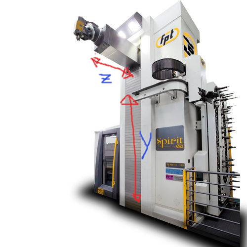
I wanted to ask for information regarding the management of a similar machine, attached.
When the Z axis leans forward, it clearly bends downwards, compromising the real machining quota for the same command quota of the y axis.
Clearly the problem is more evident when the z axis is further forward.
How would it be possible to relate the position of the Y axis in relation to the exit of the Z axis, so that when z goes forward, the y axis rises in relation?
I was thinking of an additional component, an offset, but I was asking for your ideas and experiences on the matter.
Thanks to everyone in advance
Attachments:
Last edit: 03 Aug 2024 07:27 by papagno-source.
Please Log in or Create an account to join the conversation.
- scotth
- Offline
- Elite Member
-

Less
More
- Posts: 241
- Thank you received: 61
04 Aug 2024 03:55 #306897
by scotth
Replied by scotth on topic Compensation Z axis respect at Y
Large horizontal mills with a quill will drive you crazy. The only way that I know of for correction is to use a laser scanner and develop a point cloud of X Y and Z. Starting with X0 Y0 Z0 to max travel in a grid. Then develop an error table based on measured and commanded. Remember that lights shining on the machine and room temp will cause drift. The weight of the tool will cause error. After you develop an error comp table, you can then correct the errors in the program in advance. Each axis has pitch yaw and roll, so a simple comp on Y to Z probably will not fix your problem. This is why we don't have horizontal Jig Bores.
www.faro.com/en/Resource-Library/Webinar...g-Processes-on-Track
You could try API for volumetric compensation, they can help. apimetrology.com/machine-tool-calibration/
www.faro.com/en/Resource-Library/Webinar...g-Processes-on-Track
You could try API for volumetric compensation, they can help. apimetrology.com/machine-tool-calibration/
Please Log in or Create an account to join the conversation.
- papagno-source
- Offline
- Premium Member
-

Less
More
- Posts: 113
- Thank you received: 7
04 Aug 2024 06:55 #306903
by papagno-source
Replied by papagno-source on topic Compensation Z axis respect at Y
Thanks for the reply.
I was wondering, after having obtained the map of the points, I thought of inserting them in a linuxcnc compensation file.
But the compensation file compensates errors related only to the axis involved and not to axes in mechanical relation between them, for example z with respect to y.
I thought of actually verifying the geometric displacement of y, in relation to the advancement of z and of relating them with trigonometry.
the result of the offset that varies in real time as Z moves, insert it with an offset component to the command position of the Y drives. It should work if the points taken are precise.
Please Log in or Create an account to join the conversation.
- scotth
- Offline
- Elite Member
-

Less
More
- Posts: 241
- Thank you received: 61
04 Aug 2024 15:25 #306928
by scotth
Replied by scotth on topic Compensation Z axis respect at Y
If you can get the comp correct for Y Z it will help to use W axis rather than Z for boring.
Please Log in or Create an account to join the conversation.
Time to create page: 0.080 seconds

