Why not fitting a servo motor with angular contact bearing
- PhilipME
-
 Topic Author
- Offline
- Elite Member
-

- Posts: 176
- Thank you received: 14
Not sure if the rotor is removable, and the bearing can be replaced, I would say the back bearing with a bearing that can absorb the high axial load.
Any one done such thing before or considered doing it?
Good day
Philip
Please Log in or Create an account to join the conversation.
- timo
- Offline
- Elite Member
-

- Posts: 171
- Thank you received: 50
How are you going to attach the tool holder to the motor shaft?
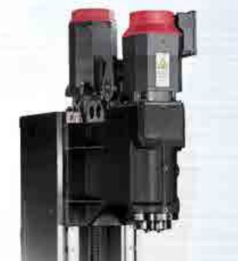
On my milling machine they put the worksspindle in a separate spindle block.
The motor sits on top of the spindle housing using one of these rubber couplers.
There is a lot going on in milling spindles.
- Tool clamp
- Active water cooling of the bearings with external cooler
- Air purging to keep debris out
- Purging of the tool taper
The motor shaft is probably not designed for lateral bending stiffness and that might be a weak link.
On the hobby machine they used a toothed belt between motor and tool spindle. Considering that the hobby machine can "snap off" 8 mm endmills when chip evacuation fails. I would not trust a 14 mm motor shaft beeing up for the job long term.
Most bread and butter VMCs still use separate units for motor and tool spindle, obviously it is cheaper and easier
Greetings Timo
Attachments:
Please Log in or Create an account to join the conversation.
- PhilipME
-
 Topic Author
- Offline
- Elite Member
-

- Posts: 176
- Thank you received: 14
But I still think for DIY machines, which are quite far from production machines, with low cutting speed, low step-in values, it can be done.
I could rap copper tube around the servo motor to remove the heat from the bearings.
But I agree, in such design the servo motor shouldn't be exposed to very high axial loads of forces, and moment.
Please Log in or Create an account to join the conversation.
- timo
- Offline
- Elite Member
-

- Posts: 171
- Thank you received: 50
I think you are still better off with purpose built equipment.
The boundries are
- rpm
- lateral stiffnes (fatigue of motor shaft)
- encoder speed
For small tools or wood you are better off with a water or air cooled AC high speed spindle. (I think a usable one for hobby can start at 300-400 USD)
For metal cutting with HSS endmills torque becomes a problem with no gearing whatsoever. When running at low rpm (slitting saw)
a 3 Nm, 1 500 W AC servo without gearing will be hopeless. Also for lower rpm work the shaft is not suitable it will fail under side load sooner or later. Despite the fact that there is no means to install any standard tooling.
A typical knee mill head with: stepped belt pulleys or gearing, proper bearings, R8 or BT30 interface and draw bar, can do quite some useful work. Even with a flimsy 2 or 3 hp motor.
So you will be better off to use a typical hobby mill ( or knee mill) setup with gear reduction. If desired change the BLDC (or AC) motor with the AC servo, Keep the gearbox or belt system.
Servos capable of running more than 10000 rpm become expensive.
I think for the DIYer it is best to decide first. High speed, or low speed. Based on that go with an air (or water) cooled AC spindle. (not crazy expensive)
Or just go the route of motor with dedicated tool spindle and gearing.
Greetings Timo
Please Log in or Create an account to join the conversation.
- PhilipME
-
 Topic Author
- Offline
- Elite Member
-

- Posts: 176
- Thank you received: 14
I doubt it can be done in a meaningful way
I was surfing and found this link (post # 7)
www.cnczone.com/forums/benchtop-machines...speeds-feed-doc.html
I bought a cylindrical ER25 toolholder from Rego-Fix (Swiss made) and NSK P4 angular contact bearings and made my own direct coupled spindle.
I did the lathe work myself. While its not perfect I am still pretty proud of it. It takes about 15 minutes to swap between the highspeed spindle and
my high torque 'grunter'.
It cuts steel like a DEMON!!!! The problem is that my mill is not really a stiff as I had thought.....but still I can cut as much steel or stainless steel as
I can offer up to the spindle.
But you made me change my mind.
This post does not tell us how long the servo motor lived. Theoriticaly, I doubt if it will live normal servo motor life.
Thanks
Please Log in or Create an account to join the conversation.
- timo
- Offline
- Elite Member
-

- Posts: 171
- Thank you received: 50
I did the lathe work myself."
I read it like he made a spindle cartridge with ER25 collet holder and, tapered bearings, the motor is in-line coupled.
In that case the motor was not modified, just attached via coupler, so the motor lives in its natural environment just putting out torque.
The thread is a good read to make up the mind. High speed, vs low speed.
Greetings Timo
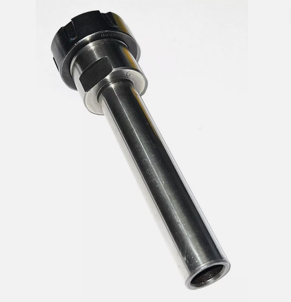
p.s. the collet holder looks like this. Usually bearings fit reasonably well on the outside. I assume that is what was used.
Attachments:
Please Log in or Create an account to join the conversation.
- PhilipME
-
 Topic Author
- Offline
- Elite Member
-

- Posts: 176
- Thank you received: 14
The quoted post says: "made my own direct coupled spindle.
I did the lathe work myself."
I read it like he made a spindle cartridge with ER25 collet holder and, tapered bearings, the motor is in-line coupled.
In that case the motor was not modified, just attached via coupler, so the motor lives in its natural environment just putting out torque.
The thread is a good read to make up the mind. High speed, vs low speed.
Greetings Timo
p.s. the collet holder looks like this. Usually bearings fit reasonably well on the outside. I assume that is what was used.
Many thanks for clarifying
I will proceed with the original plan of drive and driven mounted next to each other with pulley/belt system.
Philip
Please Log in or Create an account to join the conversation.


