C++ CadCam program development with CodeBlocks instead of QT
- Joco
-

- Offline
- Platinum Member
-

Less
More
- Posts: 532
- Thank you received: 327
26 May 2021 11:36 - 26 May 2021 11:38 #210332
by Joco
Replied by Joco on topic C++ CadCam program development with CodeBlocks instead of QT
Got my feet a little wet tonight with that sample code. After some reading added a method to create a circle like the line example. Linked it off the same “add line” button. Executed, saved dxf, reloaded and the new circle and line was there.
Obviously super simple but got me into exploring the code to find the correct entity type and seeing the object inheritance of DRW_Circle.
Also finally managed to get qtcreator behaving correctly at long last. Amazing what happens when you RTFM.
Cheers - James.
Obviously super simple but got me into exploring the code to find the correct entity type and seeing the object inheritance of DRW_Circle.
Also finally managed to get qtcreator behaving correctly at long last. Amazing what happens when you RTFM.
Cheers - James.
Last edit: 26 May 2021 11:38 by Joco.
Please Log in or Create an account to join the conversation.
- Grotius
-
 Topic Author
- Offline
- Platinum Member
-
Less
More
- Posts: 2419
- Thank you received: 2348
26 May 2021 13:05 - 26 May 2021 13:08 #210342
by Grotius
Replied by Grotius on topic C++ CadCam program development with CodeBlocks instead of QT
Hi Joco,
Ok, nice to hear !
Got my feet a little wet tonight with that sample code.
") I think you have a nice starting point. I could only manage this trough my previous research over the years.
I think you have a nice starting point. I could only manage this trough my previous research over the years.
I have done some work today and attached a new archive.
1. Created the databucket. When the dxf is loaded, data bucket is filled up. It prints output's for you.
2. When loading multiple dxf's i have integrated clean up function's for opencascade, dxfrw and databucket. They work.
3. Added the icon's archive, setted up a resource file.
4. Added the cavaliercontours library.
5. Added a stackedwidget so you can see how to code into this stackedwidget. This is helpfull to do for example settings on page 2.
Part of the message is hidden for the guests. Please log in or register to see it.
At this stage i will pause for a little time.
For you it's now ready to begin with the contour algoritme.
You can visit my github cadcam_rev repro for a algoritme. But maybe you want to write it yourself?
Let me know how you think about this.
The contour algortitme roughfly includes steps like :
1. look for open and closed contours.
2. group the primitives for every closed and open contour.
3. create a cw or ccw direction for every contour. Do a pip (point in polygon) check.
4. create a depth sequence for the contours. first cut inside products, then outside products.
5. maybe colorize inside cut's with yellow and outside cut's with red.
After this the offset's can be done.
Ok, nice to hear !
Got my feet a little wet tonight with that sample code.
I think you have a nice starting point. I could only manage this trough my previous research over the years.I have done some work today and attached a new archive.
1. Created the databucket. When the dxf is loaded, data bucket is filled up. It prints output's for you.
2. When loading multiple dxf's i have integrated clean up function's for opencascade, dxfrw and databucket. They work.
3. Added the icon's archive, setted up a resource file.
4. Added the cavaliercontours library.
5. Added a stackedwidget so you can see how to code into this stackedwidget. This is helpfull to do for example settings on page 2.
Part of the message is hidden for the guests. Please log in or register to see it.
At this stage i will pause for a little time.
For you it's now ready to begin with the contour algoritme.
You can visit my github cadcam_rev repro for a algoritme. But maybe you want to write it yourself?
Let me know how you think about this.
The contour algortitme roughfly includes steps like :
1. look for open and closed contours.
2. group the primitives for every closed and open contour.
3. create a cw or ccw direction for every contour. Do a pip (point in polygon) check.
4. create a depth sequence for the contours. first cut inside products, then outside products.
5. maybe colorize inside cut's with yellow and outside cut's with red.
After this the offset's can be done.
Attachments:
Last edit: 26 May 2021 13:08 by Grotius.
Please Log in or Create an account to join the conversation.
- Joco
-
- Offline
- Platinum Member
-
Less
More
- Posts: 532
- Thank you received: 327
27 May 2021 02:50 #210418
by Joco
Replied by Joco on topic C++ CadCam program development with CodeBlocks instead of QT
Grotius - thanks for this. Have been looking over things and at this point really just one question on the databucket implementation. More a design choices question.
If I am reading it correctly the databucket class is "empty" of data and only has some actions. The databucket data is essentially held in what I would see as global vars. To help my learning, was there a reason you did not include them in the class defintiion? This would of course necessitate the need for a (potentially?) globally accessable instance of this class being created?
Interested in the rational for the approach.
Cheers - J.
Please Log in or Create an account to join the conversation.
- Grotius
-
Topic Author
- Offline
- Platinum Member
-
Less
More
- Posts: 2419
- Thank you received: 2348
27 May 2021 08:42 - 27 May 2021 08:49 #210432
by Grotius
Replied by Grotius on topic C++ CadCam program development with CodeBlocks instead of QT
Hi Joco,
The databucket is not empty. It has some action's indeed. One is to empty the bucket.
The databucket is filled up with data after the dxf file is loaded. This filling the databucket is done from
The databucket uses indeed system wide variables with the flag "extern".
This approach you don't see much in coding examples. A few advantages:
1. You can "#include databucket" in every class you want and the variables are accesable for read and write.
2. To add a class only for data, is quite structurized and has a non-confusing effect.
3. The centrilized data class reduces passing data arguments. You need less function arguments. Its easyer to code.
4. It's easyer to focus on the main problem to solve.
4. If you want to make a spline in a class for example you can directly acces the "s.point" vector.
Otherwise you should do it like : "spline s" and then s.point={0.0.0};
Now you can do s.{0,0,0};
Downside :
1. external var's takes longer compile time.
2. setting up extern var's can be quite tricky.
3. the code style is less accepted by prof's.
But you are free to make a class with private data members. No problem.
Expanding the data bucket class could be adding function't to swap primitives.
For example swap a line startpoint with endpoint. This is needed to get the right contour direction.
The cavaliercontours need contours with primitives that are in order with start-endpoints. So i thing you need a swap function.
Also if you want to swap a spline with uneven numbers. You can use the % sign. if(avalue%0==0) to check for uneven numbers.
If you add a contour class for calculations. You could make a copy of the databucket to it. This would be handy.
At this moment the opencascade is reading the data from the dxfrw lib. An sich this is ok when the dxf is loaded.
We could change this. We could say, the opencascade read's from the databucket class.
The databucket is not empty. It has some action's indeed. One is to empty the bucket.
The databucket is filled up with data after the dxf file is loaded. This filling the databucket is done from
void MainWindow::fill_databucket()The databucket uses indeed system wide variables with the flag "extern".
This approach you don't see much in coding examples. A few advantages:
1. You can "#include databucket" in every class you want and the variables are accesable for read and write.
2. To add a class only for data, is quite structurized and has a non-confusing effect.
3. The centrilized data class reduces passing data arguments. You need less function arguments. Its easyer to code.
4. It's easyer to focus on the main problem to solve.
4. If you want to make a spline in a class for example you can directly acces the "s.point" vector.
Otherwise you should do it like : "spline s" and then s.point={0.0.0};
Now you can do s.{0,0,0};
struct spline {
    std::vector<point> points;
};
extern spline s;
Downside :
1. external var's takes longer compile time.
2. setting up extern var's can be quite tricky.
3. the code style is less accepted by prof's.
But you are free to make a class with private data members. No problem.
Expanding the data bucket class could be adding function't to swap primitives.
For example swap a line startpoint with endpoint. This is needed to get the right contour direction.
The cavaliercontours need contours with primitives that are in order with start-endpoints. So i thing you need a swap function.
Also if you want to swap a spline with uneven numbers. You can use the % sign. if(avalue%0==0) to check for uneven numbers.
If you add a contour class for calculations. You could make a copy of the databucket to it. This would be handy.
At this moment the opencascade is reading the data from the dxfrw lib. An sich this is ok when the dxf is loaded.
We could change this. We could say, the opencascade read's from the databucket class.
Last edit: 27 May 2021 08:49 by Grotius.
Please Log in or Create an account to join the conversation.
- Joco
-
- Offline
- Platinum Member
-
Less
More
- Posts: 532
- Thank you received: 327
27 May 2021 22:30 #210476
by Joco
Replied by Joco on topic C++ CadCam program development with CodeBlocks instead of QT
Grotius - thanks for the response. Understand the rational. For how we will be using the chunk of data having a simple model for global access makes sense.
What I have been wondering about is HOW this data will be used and looking at the setup at the moment (which I am guessing was an initial starting point and not "end game") I think we are loosing too much context from the dxf. But I am equally happy to be told why they doesn't matter.") Anyway, here is my line of thinking for your critique.
Anyway, here is my line of thinking for your critique.
[1] Layer info and knowing what entities are in what layer can be quite useful. It allows the possibility of information via the layer name being part of the dxf and being utilised by the tool to get hints on processing the entities in that layer. It could also be useful later in the UI if you want to be able to hide or colour things based on what layer it is in.
[2] Thinking about the concept of a Shape. Something that I think the dxf file has even if it is not called that. If I look at the sample dxf in librecad it treats the entire outline of the "hello" as a single entity. You click on that line and it is selected in its entirety. I believe that is because the dxf records it as an entity with a list of associated geometry. So when you select any of that geometry the entire entity can be selected. At the moment we have a collection of geometry entities that are associated by type not by what overall shape thy belong to. At least I think that is the case.
[3] I think there would also be a ShapePath that would probably subclass of Shape. This would be the representation of a tool path for a shape. If you think about the operation idea (see next) then you could possibly have multiple paths for a shape that are 1:1 associated to an operation driving the specifics of that path.
[4] Thinking forward to the idea of an Operation which can be associated to 1 or more Shapes. Operations being how we would describe tool to use, cut speeds, number of passes etc etc. I think an operation would hold a 1:1 relationship to a ShapePath
If the resulting object graph from the above objects/relationships was available globally then it would make easy access for the opencascade side of things to do what it needs to (e.g. load for visualisation, support full entity selection, maybe layer visibility toggling) and for the contour processing and eventual gcode generation stuff where we work out tool paths, offset calculation, cut direction etc etc.
Keen for your views as I want to get my thinking straighten out and aligned before I start hacking away.
Cheers - J
What I have been wondering about is HOW this data will be used and looking at the setup at the moment (which I am guessing was an initial starting point and not "end game") I think we are loosing too much context from the dxf. But I am equally happy to be told why they doesn't matter.
Anyway, here is my line of thinking for your critique.[1] Layer info and knowing what entities are in what layer can be quite useful. It allows the possibility of information via the layer name being part of the dxf and being utilised by the tool to get hints on processing the entities in that layer. It could also be useful later in the UI if you want to be able to hide or colour things based on what layer it is in.
[2] Thinking about the concept of a Shape. Something that I think the dxf file has even if it is not called that. If I look at the sample dxf in librecad it treats the entire outline of the "hello" as a single entity. You click on that line and it is selected in its entirety. I believe that is because the dxf records it as an entity with a list of associated geometry. So when you select any of that geometry the entire entity can be selected. At the moment we have a collection of geometry entities that are associated by type not by what overall shape thy belong to. At least I think that is the case.
[3] I think there would also be a ShapePath that would probably subclass of Shape. This would be the representation of a tool path for a shape. If you think about the operation idea (see next) then you could possibly have multiple paths for a shape that are 1:1 associated to an operation driving the specifics of that path.
[4] Thinking forward to the idea of an Operation which can be associated to 1 or more Shapes. Operations being how we would describe tool to use, cut speeds, number of passes etc etc. I think an operation would hold a 1:1 relationship to a ShapePath
If the resulting object graph from the above objects/relationships was available globally then it would make easy access for the opencascade side of things to do what it needs to (e.g. load for visualisation, support full entity selection, maybe layer visibility toggling) and for the contour processing and eventual gcode generation stuff where we work out tool paths, offset calculation, cut direction etc etc.
Keen for your views as I want to get my thinking straighten out and aligned before I start hacking away.
Cheers - J
Please Log in or Create an account to join the conversation.
- Grotius
-
Topic Author
- Offline
- Platinum Member
-
Less
More
- Posts: 2419
- Thank you received: 2348
28 May 2021 09:16 - 28 May 2021 09:17 #210503
by Grotius
Replied by Grotius on topic C++ CadCam program development with CodeBlocks instead of QT
Hi Joco,
) I think we are loosing too much context from the dxf.
It's good to save more dxf content into the databucket. Layer's and color's are good to add.
Then you can indeed do a operation based on a layer or color.
I think you can try to add more info. If you have problem's doing this, just give a call.
For info. You can set the primitive colors in opencascade based on rgba values.
librecad it treats the entire outline of the "hello" as a single entity.
That is correct. It is more a coincedence with this drawing. It's a lwpolyline. I coded to convert this into line's already.
For the cam you have to go for lines and arc's to stay gcode compatible.
If you think in splines, ellipses or lwpolylines, linuxcnc can not deal this primitives.
Inkscape saves splines and ellipses as lines in dxf.
In the end you can only use lines and arc's for the gcode processing.
Then for the coding it's easy to convert splines, ellipses, lwpolylines etc into lines. I have example's function's on the git for this.
Then for the coding there is only left line and arc's.
This make's your code quite compact.
When you are thinking about this, it's possible to convert splines into arc' segments.
When linucxcnc's gcode was able to do 3darc, 3dspline etc. This primitves are used in the robot program for path planning.
Then we could act on that for the cam program.
I think there would also be a ShapePath that would probably subclass of Shape.
That is correct. You could save this data with the operation list.
Thinking forward to the idea of an Operation which can be associated to 1 or more Shapes. Operations being how we would describe tool to use, cut speeds, number of passes etc etc.
Yes.
If the resulting object graph from the above objects/relationships was available globally then it would make easy access for the opencascade side of things to do what it needs
When you have done a operation, you want to visualize the data.
Within the operation data, there will be also a chuck of opencascade meat.
Opencascade then display's the content. We do this from a vector bucket. So when the bucket is empty, nothing is showed.
And from the primitivestruct you can toggle visibility with a bool flag relating to layer.
Ok have a nice day !
Last edit: 28 May 2021 09:17 by Grotius.
Please Log in or Create an account to join the conversation.
- Joco
-
- Offline
- Platinum Member
-
Less
More
- Posts: 532
- Thank you received: 327
29 May 2021 00:43 #210576
by Joco
Replied by Joco on topic C++ CadCam program development with CodeBlocks instead of QT
Thanks ... happily hacking away and learning.
Please Log in or Create an account to join the conversation.
- Joco
-
- Offline
- Platinum Member
-
Less
More
- Posts: 532
- Thank you received: 327
29 May 2021 11:55 - 29 May 2021 11:57 #210616
by Joco
Replied by Joco on topic C++ CadCam program development with CodeBlocks instead of QT
Ok. Ive got a rough working implementation of a databucket using an object graph of the following top down structure:The Geometry class instances is one of the following derived classes from the base Geom class: Point, Line, Arc, Circle. I am still toying with splines as they can be represented using gcode. But the others are safer from a gcode perspective.
So next is to convert the visualisation to drive off the databucket.
Bit of a learning curve but getting there.
Cheers.
Databucket
 |
/|\
Layer
 |
/|\
Shape
 |
/|\
Geometry So next is to convert the visualisation to drive off the databucket.
Bit of a learning curve but getting there.
Cheers.
Last edit: 29 May 2021 11:57 by Joco.
The following user(s) said Thank You: tommylight
Please Log in or Create an account to join the conversation.
- Joco
-
- Offline
- Platinum Member
-
Less
More
- Posts: 532
- Thank you received: 327
30 May 2021 22:49 #210756
by Joco
Replied by Joco on topic C++ CadCam program development with CodeBlocks instead of QT
Learning continues. Have moved the visualisation load to operate off the databucket. Can't seem to get the colours to change to something with a better contrast in the UI even though I have them set as I want in qtdesigner. Not sure what is happening there.
Also fighting with the conversion of the polyline bulge + line concept to create an arc. Too long since high school and all that kind of triangle/circle stuff. The only online examples I have found are in lisp. So who knows what other alterations are happening under the hood in those functions.
Cheers - J.
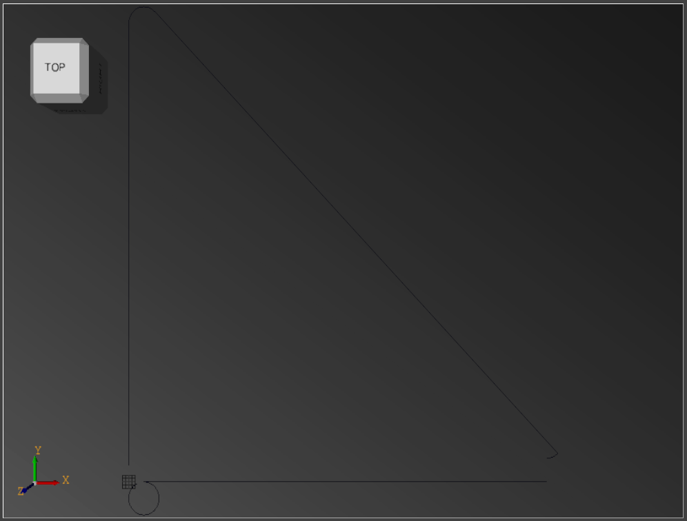
Attachments:
Please Log in or Create an account to join the conversation.
- Joco
-
- Offline
- Platinum Member
-
Less
More
- Posts: 532
- Thank you received: 327
31 May 2021 00:32 #210763
by Joco
Replied by Joco on topic C++ CadCam program development with CodeBlocks instead of QT
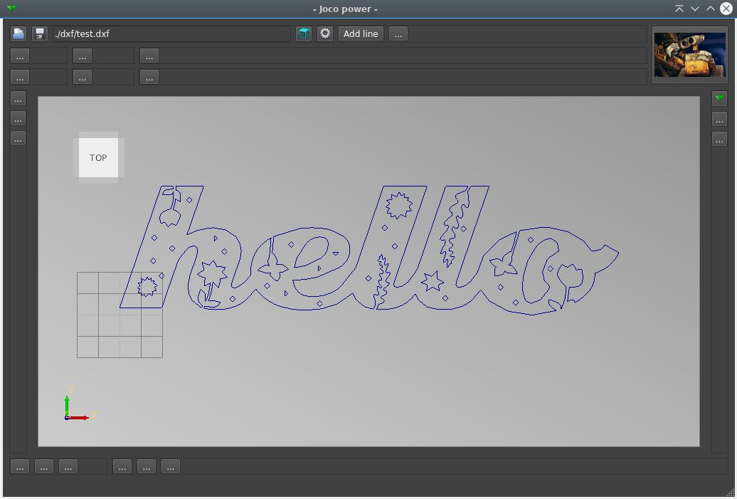
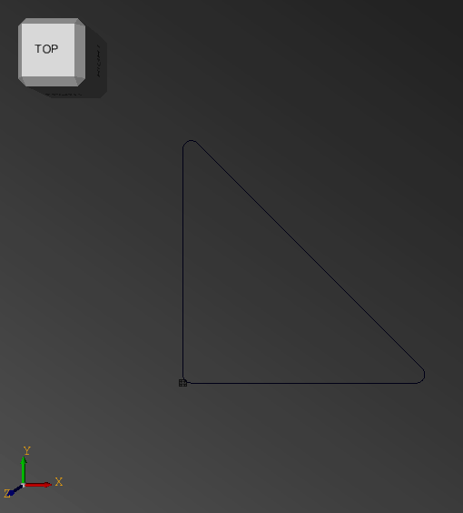
Well a bit of reading into how the dxf2gcode code base deals with these curves and some clearer maths examples and we seem to be winning a little bit. Following screen samples all based off a loaded databucket with geom occ paint methods in the relevant geometry class. No more reading the dxf file once its loaded into the databucket.
Fixed version of last post:
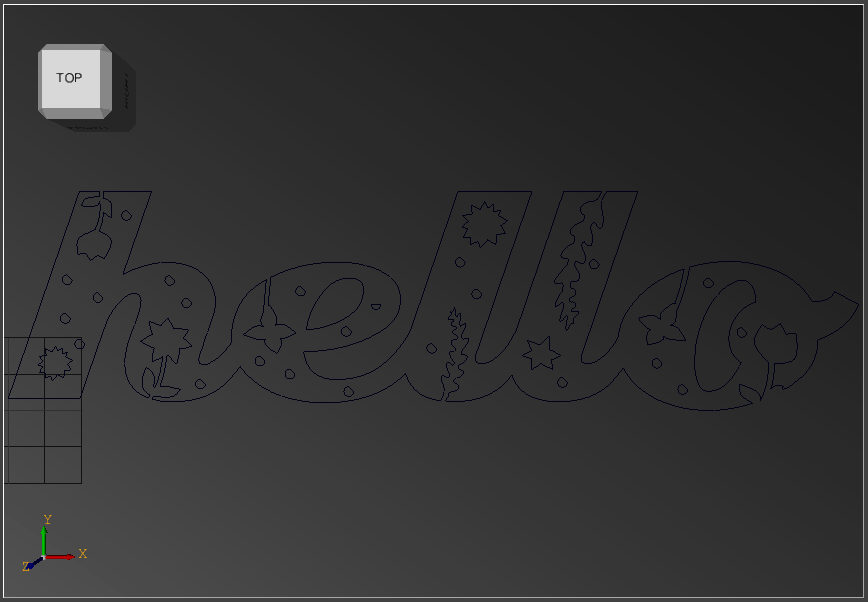
And the "master" test file:
Fixed version of last post:
And the "master" test file:
Attachments:
Please Log in or Create an account to join the conversation.
Time to create page: 0.233 seconds