Probing and automatic tool length measurements
- cahlfors
- Offline
- Junior Member
-

Less
More
- Posts: 39
- Thank you received: 3
18 Nov 2015 19:31 - 18 Jul 2018 22:03 #65456
by cahlfors
Probing and automatic tool length measurements was created by cahlfors
I think most of us are amateurs without automatic tool changers and since a fresh install has no help for us, I would like to share my reasonably working setup in the hope to get others up and running and perhaps get some suggestions for improvement or alternate solutions. So, please contribute with your experience or suggestions!
I am using a reasonably cheap 3D-probe from Usovo and a tool length (TLO) probe. These are electrically connected to the same pin on the parallel port and are normally closed (NC). The reason for using the same pin is that any probe commands use the same signal anyway, so there is no use trying to keep them separate. I found that out the hard way.
Here is what they look like:
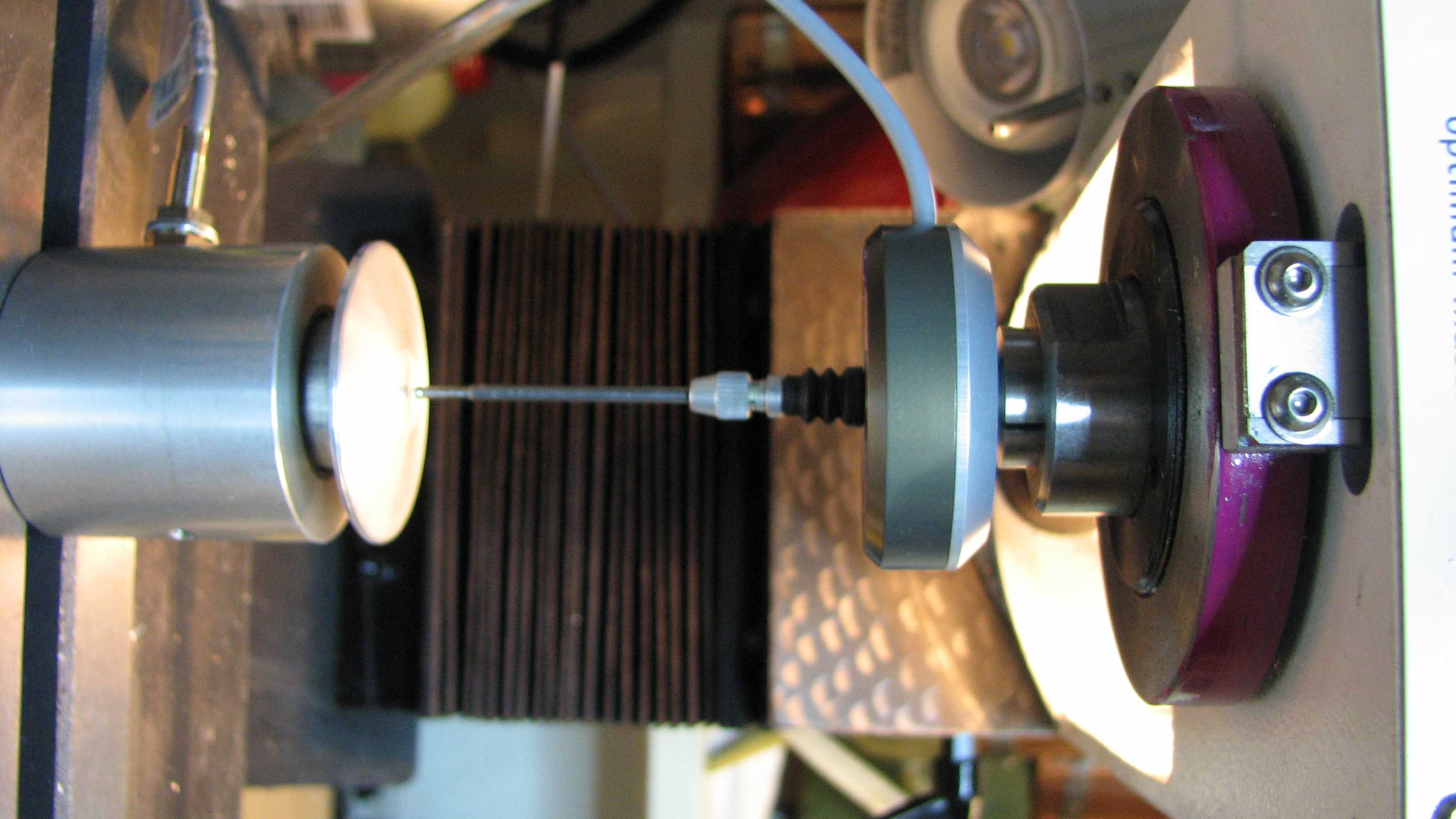
The picture gets rotated 90deg clockwise here for some reason.
What you see in the collet is the 3D probe and below that, the TLO probe, a commercial product based on a proximity switch you see sticking out from the side. The tool never gets close to the proximity switch itself, so tool size should not matter.
For tool length measurement, I have used this system:
github.com/LinuxCNC/linuxcnc/tree/master...h-tool-length-switch
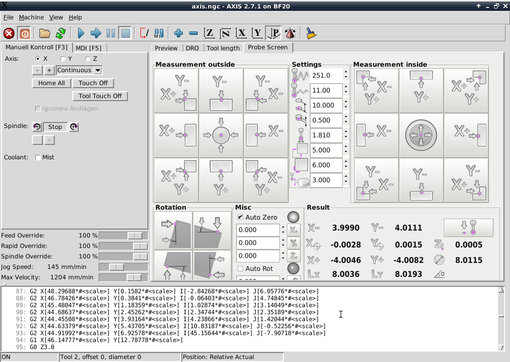
Screen shot:

I have managed to add a "reset" button to this GUI. The purpose of this is to clear any active settings. The next challenge is to make the button do something...")
For probing the material corners, finding centers etc, I have used verser's system, described here:
The forum does not allow adding link here, unfortunately, but perhaps you can search for author = verser and find the below...
screen shot:
Conf files and code changes coming...
The BF20.ini file:
There is a name clash between the tool length screen and 3d probe screen and I changed the "gladevcp" name in the probe screen to "gladevcpprobe" instead:
BF20.hal:
In order to support both a 3D probe and a TLO probe, I added an OR function together with debounce (for the 3D probe):
The work process seems to be this:
As mentioned. I start by measuring my 3D probe, which is my reference tool. For that to be possible, the spring in the TLO probe has to be weaker than that in the 3D probe. We want the 3D probe to be measured the same way as any other tool. If the 3D probe spring is too weak, it will trip first and the reference length will be wrong.
Remaining issues:
/Chris
I am using a reasonably cheap 3D-probe from Usovo and a tool length (TLO) probe. These are electrically connected to the same pin on the parallel port and are normally closed (NC). The reason for using the same pin is that any probe commands use the same signal anyway, so there is no use trying to keep them separate. I found that out the hard way.
Here is what they look like:
The picture gets rotated 90deg clockwise here for some reason.
What you see in the collet is the 3D probe and below that, the TLO probe, a commercial product based on a proximity switch you see sticking out from the side. The tool never gets close to the proximity switch itself, so tool size should not matter.
For tool length measurement, I have used this system:
github.com/LinuxCNC/linuxcnc/tree/master...h-tool-length-switch
Screen shot:
I have managed to add a "reset" button to this GUI. The purpose of this is to clear any active settings. The next challenge is to make the button do something...
For probing the material corners, finding centers etc, I have used verser's system, described here:
The forum does not allow adding link here, unfortunately, but perhaps you can search for author = verser and find the below...
screen shot:
Conf files and code changes coming...
The BF20.ini file:
There is a name clash between the tool length screen and 3d probe screen and I changed the "gladevcp" name in the probe screen to "gladevcpprobe" instead:
EMBED_TAB_NAME=Tool length
EMBED_TAB_COMMAND=halcmd loadusr -Wn gladevcp gladevcp -c gladevcp -u python/gladevcp-handler.py -x {XID} manualtoolchange.ui
EMBED_TAB_NAME=Probe Screen
EMBED_TAB_COMMAND=halcmd loadusr -Wn gladevcp gladevcp -c gladevcpprobe -u python/probe_screen.py -x {XID} probe_icons/probe_screen.glade BF20.hal:
In order to support both a 3D probe and a TLO probe, I added an OR function together with debounce (for the 3D probe):
loadrt or2 count=1
addf or2.0 base-thread
net my-sigin1 or2.0.in0 <= parport.0.pin-15-in
net my-sigin2-raw parport.1.pin-10-in => debounce.0.0.in
net my-sigin2-filt or2.0.in1 <= debounce.0.0.out
#net my-sigin2 or2.0.in1 <= parport.1.pin-10-in
net probe-in motion.probe-input <= or2.0.out
setp debounce.0.delay 90
The work process seems to be this:
- Issue an M2 and G49 to clear any settings and offsets in use. I do not like this step, but it seems necessary. I would like to have this done implicitly when starting a new operation - it is so easy to forget...

- Issue M6 T1. The machine now moves to the tool change location in the top position.
- Mount the 3D probe, click "reference tool" in the GUI and then "change complete" to start probing.
- I then move to my workpiece and set my x, y and z offsets with the help of verser's GUI.
- Now, execution of the g code can start. The machine will move to the tool change position and the first real tool can be loaded, "reference tool" unselected and "change complete" clicked to start measuring the new tool.
- G code executes as usual. Change tool when prompted and hit "change complete".
As mentioned. I start by measuring my 3D probe, which is my reference tool. For that to be possible, the spring in the TLO probe has to be weaker than that in the 3D probe. We want the 3D probe to be measured the same way as any other tool. If the 3D probe spring is too weak, it will trip first and the reference length will be wrong.
Remaining issues:
- Clearing of previous settings before starting a new operation.
- The "program counter" jumps all over the place. Is that what they call "preview broken"? I need to fix that!
- TLO measurement is far too inexact currently (0.2mm error). People tell me I need to probe slowly. I do not understand why; LinuxCNC knows the exact machine coordinates at each time increment in my thinking, but I will give it a try./li]
/Chris
Last edit: 18 Jul 2018 22:03 by cahlfors. Reason: Github move
Please Log in or Create an account to join the conversation.
- cahlfors
- Offline
- Junior Member
-
Less
More
- Posts: 39
- Thank you received: 3
21 Nov 2015 12:43 - 22 Nov 2015 10:13 #65597
by cahlfors
Replied by cahlfors on topic Probing and automatic tool length measurements
Apparently I am abusing the forum with too many attachments. So here is the continuation in a new post..
gladevcp.hal
I do not remember if I made any changes here.
manualtoolchange.hal
The TLO stuff did absolutely nothing in its standard configuration. I had to make this very important addition:
I will check if there was something more I did.
Yes, there was. This part is also important and slightly modified to make it work:
Thanks,
/Chris
gladevcp.hal
I do not remember if I made any changes here.
manualtoolchange.hal
The TLO stuff did absolutely nothing in its standard configuration. I had to make this very important addition:
# loop prepare signals when remapping T
 net tool-prep-loop iocontrol.0.tool-prepare iocontrol.0.tool-prepared
I will check if there was something more I did.
Yes, there was. This part is also important and slightly modified to make it work:
Thanks,
/Chris
Last edit: 22 Nov 2015 10:13 by cahlfors. Reason: added manual_change.ngc
Please Log in or Create an account to join the conversation.
- cncbasher
- Offline
- Moderator
-

Less
More
- Posts: 1021
- Thank you received: 202
21 Nov 2015 20:19 - 21 Nov 2015 20:20 #65619
by cncbasher
Replied by cncbasher on topic Probing and automatic tool length measurements
chris , could you post your tool change ( tool length ) panel
Last edit: 21 Nov 2015 20:20 by cncbasher.
Please Log in or Create an account to join the conversation.
- cahlfors
- Offline
- Junior Member
-
Less
More
- Posts: 39
- Thank you received: 3
21 Nov 2015 20:27 #65621
by cahlfors
Replied by cahlfors on topic Probing and automatic tool length measurements
It's the second picture above
Please Log in or Create an account to join the conversation.
- cncbasher
- Offline
- Moderator
-
Less
More
- Posts: 1021
- Thank you received: 202
21 Nov 2015 20:42 #65623
by cncbasher
Replied by cncbasher on topic Probing and automatic tool length measurements
the glade .ui or xml Chris ?
Please Log in or Create an account to join the conversation.
- cahlfors
- Offline
- Junior Member
-
Less
More
- Posts: 39
- Thank you received: 3
22 Nov 2015 10:17 #65650
by cahlfors
This version is with my non-functioning reset button, if that is what you are after.
The original is here:
git.linuxcnc.org/gitweb?p=linuxcnc.git;a...ch;hb=refs/heads/2.6
/Chris
Replied by cahlfors on topic Probing and automatic tool length measurements
This version is with my non-functioning reset button, if that is what you are after.
The original is here:
git.linuxcnc.org/gitweb?p=linuxcnc.git;a...ch;hb=refs/heads/2.6
/Chris
Please Log in or Create an account to join the conversation.
- cncbasher
- Offline
- Moderator
-
Less
More
- Posts: 1021
- Thank you received: 202
22 Nov 2015 10:27 #65651
by cncbasher
Replied by cncbasher on topic Probing and automatic tool length measurements
thanks Chris ,
Please Log in or Create an account to join the conversation.
- cahlfors
- Offline
- Junior Member
-
Less
More
- Posts: 39
- Thank you received: 3
22 Nov 2015 15:57 #65656
by cahlfors
Replied by cahlfors on topic Probing and automatic tool length measurements
Issue #3 solved!
Indeed, probing slowly imrpoved error from 0.2mm down to 0.04mm. I just measured the z backlash to 0.03mm, so this is as good as it gets right now!") I will have to work on the backlash, but leave that for the day when I really need it. It seems more important to speed up probing. Waiting for the mill to go from the top all the way down to the TLO sensor at slow speed is so so...
I will have to work on the backlash, but leave that for the day when I really need it. It seems more important to speed up probing. Waiting for the mill to go from the top all the way down to the TLO sensor at slow speed is so so... 
Thanks,
/Chris
Indeed, probing slowly imrpoved error from 0.2mm down to 0.04mm. I just measured the z backlash to 0.03mm, so this is as good as it gets right now!
I will have to work on the backlash, but leave that for the day when I really need it. It seems more important to speed up probing. Waiting for the mill to go from the top all the way down to the TLO sensor at slow speed is so so... Thanks,
/Chris
Please Log in or Create an account to join the conversation.
- cncbasher
- Offline
- Moderator
-
Less
More
- Posts: 1021
- Thank you received: 202
22 Nov 2015 16:04 #65658
by cncbasher
Replied by cncbasher on topic Probing and automatic tool length measurements
what probing code are you using Chris ?
you can move down to near the switch at a faster speed and then slow down for say the last inch or so
you can move down to near the switch at a faster speed and then slow down for say the last inch or so
Please Log in or Create an account to join the conversation.
- cahlfors
- Offline
- Junior Member
-
Less
More
- Posts: 39
- Thank you received: 3
22 Nov 2015 17:01 #65661
by cahlfors
Replied by cahlfors on topic Probing and automatic tool length measurements
"manual_change.ngc" at the bottom of post #65597 above.
Understanding how it executes beats me. It is not sequential von Neumann style execution. Different threads execute different parts of it in an order that I do not understand. Modifying it will be a challenge.
Slowing down before hitting the sensor seems impossible, as the machine would not know it is close to the sensor before it trips.I think I should look at verser's 3D probe code. He hits the object at "high" speed, moves back and then goes very slowly. That should work for TLO purpose, too, I am thinking.
Thanks,
/Chris
Please Log in or Create an account to join the conversation.
Time to create page: 0.162 seconds