- LinuxCNC
- General LinuxCNC Questions
- Setting up Closed loop Spindle speed control and Feedback (0-10V Analog)
Setting up Closed loop Spindle speed control and Feedback (0-10V Analog)
- denhen89
-
 Topic Author
- Offline
- Elite Member
-

Less
More
- Posts: 301
- Thank you received: 27
03 Aug 2020 17:27 - 03 Aug 2020 18:07 #177059
by denhen89
Setting up Closed loop Spindle speed control and Feedback (0-10V Analog) was created by denhen89
(Machine: Lathe, Card: Mesa 7i76e, VFD: Toshiba VF-S11, Spindle Encoder: Omron E6B2-CWZ1X 100ppr)
Hello guys,
since about 2 weeks i am stuck at setting up my VFD. I will not write down what i have tried the last 2 or even 3 weeks, but to make it as short as possible, i wanted to control the spindle motor through Modbus. I exchanged a lot of mails with the author of the VFS11 VFD Driver : linuxcnc.org/docs/2.8/html/drivers/vfs11.html. He helped me a lot to build my own converter, which should work (works on 2 different PCs - tested with the windows "Tera Term" software and on Linux with "picocom") but unfortunately the VFD does not want to communicate, so i gave up and decided to control the spindle with 0-10V Analog signal.
Unfortunately its not accurate as on my CNC Router where the spindle is controlled through Modbus. (huanyang vfd)
The Max RPM should be 1420 rpm at 50Hz. Everything is set up correctly in the VFD. Here are 2 examples (please take a look at the bottom of the .IN file - i have also attached the .HAL file):
example 1:
OUTPUT_MIN_LIMIT = 0
OUTPUT_MAX_LIMIT = 1420
OUTPUT_SCALE = 1420.0
With those settings the encoder.00.velocity-rpm parameter (not sure if that parameter name is correct - i am not at the lathe PC) is showing about (jumping around a bit):
- 80 rpm when it should be 100 rpm
- about 1500 rpm when it should be 1420 rpm
example 2:
OUTPUT_MIN_LIMIT = 150
OUTPUT_MAX_LIMIT = 1420
OUTPUT_SCALE = 1420.0
With those settings the encoder.00.velocity-rpm parameter is showing 100rpm when it should be 100 and about 1480 when it should be 1420.
Thats the first problem. I thought to to use pwm signal, but to be honest, i dont know if i can control that VFD with pwm signal, so i was looking for a solution and found that page: Closed Loop Spindle .Speed Control . Unfortunately that example is for PWM signal and i dont know how to set it up with Analog signal control
The other problem is that i get not spindle feedback but the encoder is wired for sure correctly and in the hal meter i can see at the encoder.00.xxxxx commands that the encoder is also connected with Linuxcnc. I am pretty sure that something is missing in the file, but i cant figure out what.
I hope you could take a look at my configs and help me out with those problems. I have some other files like the postgui files for some physical buttons and potentiometers, so please let me know if i should upload them.
Thanks in advance
br,
Denis
Last edit: 03 Aug 2020 18:07 by denhen89.
Please Log in or Create an account to join the conversation.
- cmorley
- Offline
- Moderator
-

Less
More
- Posts: 7343
- Thank you received: 2164
03 Aug 2020 18:03 #177061
by cmorley
Replied by cmorley on topic Setting up Closed loop Spindle speed control and Feedback (0-10V Analog)
I don't see the config files.
Please Log in or Create an account to join the conversation.
- denhen89
-
Topic Author
- Offline
- Elite Member
-
Less
More
- Posts: 301
- Thank you received: 27
03 Aug 2020 18:07 #177063
by denhen89
Replied by denhen89 on topic Setting up Closed loop Spindle speed control and Feedback (0-10V Analog)
sorry, uploaded now.I don't see the config files.
Please Log in or Create an account to join the conversation.
- Todd Zuercher
-

- Away
- Platinum Member
-

Less
More
- Posts: 4764
- Thank you received: 1464
03 Aug 2020 20:36 #177085
by Todd Zuercher
Replied by Todd Zuercher on topic Setting up Closed loop Spindle speed control and Feedback (0-10V Analog)
I might be wrong, but I think it might be a good idea to get the spindle working open loop (without using the PID) before trying to run it closed loop. (I think setting FF1=1 and all other PID settings=0 will achieve this.)
Please Log in or Create an account to join the conversation.
- denhen89
-
Topic Author
- Offline
- Elite Member
-
Less
More
- Posts: 301
- Thank you received: 27
03 Aug 2020 20:49 #177089
by denhen89
Thanks Todd.
Actually i do not understand why i should first run it open loop. Easier to scale it or what do you mean.
The problem is that i do not know if something is missing in the .HAL .
Also, i should see bouncing RPM from the encoder in gmocappy speed display instead of a fixed value that i typed in by a M3 S command.
Replied by denhen89 on topic Setting up Closed loop Spindle speed control and Feedback (0-10V Analog)
I might be wrong, but I think it might be a good idea to get the spindle working open loop (without using the PID) before trying to run it closed loop. (I think setting FF1=1 and all other PID settings=0 will achieve this.)
Thanks Todd.
Actually i do not understand why i should first run it open loop. Easier to scale it or what do you mean.
The problem is that i do not know if something is missing in the .HAL .
Also, i should see bouncing RPM from the encoder in gmocappy speed display instead of a fixed value that i typed in by a M3 S command.
Please Log in or Create an account to join the conversation.
- Todd Zuercher
-
- Away
- Platinum Member
-
Less
More
- Posts: 4764
- Thank you received: 1464
04 Aug 2020 12:49 #177233
by Todd Zuercher
Replied by Todd Zuercher on topic Setting up Closed loop Spindle speed control and Feedback (0-10V Analog)
Simply because it is removing a complicated variable from the equation. Testing open loop will allow you to make sure every thing is set up right before you start trying to tune the PID loop. Things like making sure your scales are set correctly, the VFD is configured right and all of it's connections are correct (both physical and in hal).
A real RPM value read from an encoder will never be an exact precise constant value compared to the commanded . How steady it is will depend on a number of factors, including the quality and precision of your encoder, the mechanics of your system and how well you tune your PID loop. It will be jumpiest at low speeds when encoder counts are few and far between. It could be advantageous to add a low-pass filter to the value used for the display.
A real RPM value read from an encoder will never be an exact precise constant value compared to the commanded . How steady it is will depend on a number of factors, including the quality and precision of your encoder, the mechanics of your system and how well you tune your PID loop. It will be jumpiest at low speeds when encoder counts are few and far between. It could be advantageous to add a low-pass filter to the value used for the display.
Please Log in or Create an account to join the conversation.
- PCW
-

- Offline
- Moderator
-
Less
More
- Posts: 17996
- Thank you received: 5283
04 Aug 2020 13:44 #177245
by PCW
Replied by PCW on topic Setting up Closed loop Spindle speed control and Feedback (0-10V Analog)
Actually you want FF0 = 1 and all others 0 for open loop spindle control
That's because the PID input and output are the same order (both velocity)
Tuning spindle PID loops can be a bit tricky and verifying
correct open loop operation can save a lot of time
That's because the PID input and output are the same order (both velocity)
Tuning spindle PID loops can be a bit tricky and verifying
correct open loop operation can save a lot of time
Please Log in or Create an account to join the conversation.
- denhen89
-
Topic Author
- Offline
- Elite Member
-
Less
More
- Posts: 301
- Thank you received: 27
04 Aug 2020 19:10 - 04 Aug 2020 19:22 #177268
by denhen89
Replied by denhen89 on topic Setting up Closed loop Spindle speed control and Feedback (0-10V Analog)
Thanks Todd and PCW.
I did what you both wrote: FF0: 1 , all other set to 0 (P, I ,D and FF1 and FF2)
With those setting and min. speed set to 150, i get quiet accurate rpm from 150 to 500.
At e.g. S800 the rpm is between 810 and 860 (jumps around)
At S1420 the rpm is between 1450 and 1500
On the motor plate it reads that at 50hz the motor should run 1420 rpm, so i "had" set the max speed to 1420 rpm, but then i changed it to 1480 to see what happens.
I uploaded a video to youtube when i changed the speeds: YOUTUBE: Linuxcnx - 0-10v Analog spindle control
I then tried to set up the scale of the 0-10v, but it does not work as it should or as it is described.
Please take a look at the picture: (i marked the 2 lines where i had to put a "#" before the parameter)
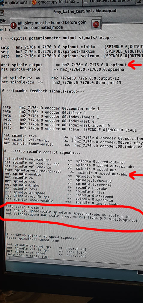
I first tried it with "spindle.0.speed-out, but there was no reaction from the VFD, so i changed to spindle.0.speed-out-abs, which works, but take a look at the scale value: "1" instead of (in my case) 0.007.
When measuring the outout voltage of the analog signal on the Mesa 7i76e i get at full speed/50hz = 10.2 Volts
So, this is my calculation: 10,2 Volt / 1420 rpm = 0,007183.....
I am sorry that i am not describing it more clearly, but i am really a bit tired of that.
I just want a quiet accurate spindle speed and also be able to use "constag surface speed".
Synchronization seems to work:
I did a dry test with a Threading g-code. I have started the programm - axis waits for spindle at speed, then starts threading. I paused the programm and made to spindle to not turn and turned it then by hand. Axis moves when turning spindle, but does not move when spindle is not turning.
Br,
Denis
I did what you both wrote: FF0: 1 , all other set to 0 (P, I ,D and FF1 and FF2)
With those setting and min. speed set to 150, i get quiet accurate rpm from 150 to 500.
At e.g. S800 the rpm is between 810 and 860 (jumps around)
At S1420 the rpm is between 1450 and 1500
On the motor plate it reads that at 50hz the motor should run 1420 rpm, so i "had" set the max speed to 1420 rpm, but then i changed it to 1480 to see what happens.
I uploaded a video to youtube when i changed the speeds: YOUTUBE: Linuxcnx - 0-10v Analog spindle control
I then tried to set up the scale of the 0-10v, but it does not work as it should or as it is described.
Please take a look at the picture: (i marked the 2 lines where i had to put a "#" before the parameter)
I first tried it with "spindle.0.speed-out, but there was no reaction from the VFD, so i changed to spindle.0.speed-out-abs, which works, but take a look at the scale value: "1" instead of (in my case) 0.007.
When measuring the outout voltage of the analog signal on the Mesa 7i76e i get at full speed/50hz = 10.2 Volts
So, this is my calculation: 10,2 Volt / 1420 rpm = 0,007183.....
I am sorry that i am not describing it more clearly, but i am really a bit tired of that.
I just want a quiet accurate spindle speed and also be able to use "constag surface speed".
Synchronization seems to work:
I did a dry test with a Threading g-code. I have started the programm - axis waits for spindle at speed, then starts threading. I paused the programm and made to spindle to not turn and turned it then by hand. Axis moves when turning spindle, but does not move when spindle is not turning.
Br,
Denis
Attachments:
Last edit: 04 Aug 2020 19:22 by denhen89.
Please Log in or Create an account to join the conversation.
- Mike_Eitel
-

- Offline
- Platinum Member
-
Less
More
- Posts: 1052
- Thank you received: 183
04 Aug 2020 19:30 #177270
by Mike_Eitel
Replied by Mike_Eitel on topic Setting up Closed loop Spindle speed control and Feedback (0-10V Analog)
Listening to the sound i doubt that your speed is jumping. I think you need to filter the encoders signal. Somebody else can chime in how to...
Do not try to adjust any loop before , you'll get crazy ;-()
Do not try to adjust any loop before , you'll get crazy ;-()
Please Log in or Create an account to join the conversation.
- denhen89
-
Topic Author
- Offline
- Elite Member
-
Less
More
- Posts: 301
- Thank you received: 27
04 Aug 2020 19:33 #177271
by denhen89
Replied by denhen89 on topic Setting up Closed loop Spindle speed control and Feedback (0-10V Analog)
Yes, you are right, but I do have already a lowpass component but no matter what value I set, there is no visible change.
Something is not correct, but i uploaded my ini and hal file, so it would be great if someone can take a look at this. I really have me best to get it done by my self.
Something is not correct, but i uploaded my ini and hal file, so it would be great if someone can take a look at this. I really have me best to get it done by my self.
Please Log in or Create an account to join the conversation.
- LinuxCNC
- General LinuxCNC Questions
- Setting up Closed loop Spindle speed control and Feedback (0-10V Analog)
Time to create page: 0.157 seconds