- LinuxCNC
- General LinuxCNC Questions
- wiring & wizard setting for minimal working of simple normal closed limit switch
wiring & wizard setting for minimal working of simple normal closed limit switch
- suraj9735
-
 Topic Author
- Offline
- Senior Member
-

Less
More
- Posts: 77
- Thank you received: 1
18 Feb 2021 13:51 #199251
by suraj9735
wiring & wizard setting for minimal working of simple normal closed limit switch was created by suraj9735
Dear Forum,
With your help, I am able to run the X,Y, Z motors and thanks for everything.
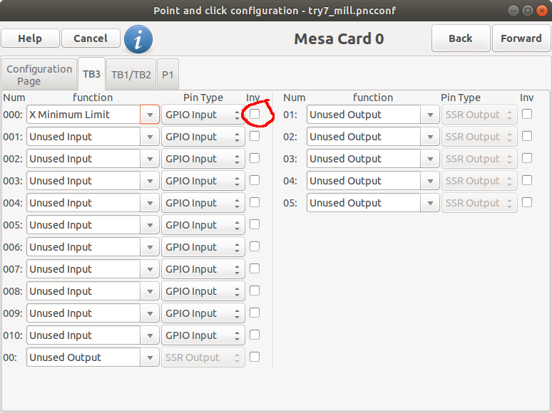
Now I want to connect my simple normal closed type limit switch for x axis only for testing to the mesa 7i95 card. but it gives "joint 0 limit switch error". If I remove the negative X limit setting, it's working fine in jog/MDI mode. It seems I have error in setting home location (30,30,30) position and limit switch position setting. I have attached all the wiring and setting.
I connect limit common pin to input pin 1 and NC pin to the ground of step0. Is the wiring OK?
Please Log in or Create an account to join the conversation.
- bevins
-

- Offline
- Platinum Member
-

Less
More
- Posts: 1940
- Thank you received: 338
18 Feb 2021 13:57 #199252
by bevins
I dont know about the wiring of that board but you are using N/C so you need to "not" the input. That would be my guess.
Replied by bevins on topic wiring & wizard setting for minimal working of simple normal closed limit switch
Dear Forum,
With your help, I am able to run the X,Y, Z motors and thanks for everything.
Now I want to connect my simple normal closed type limit switch for x axis only for testing to the mesa 7i95 card. but it gives "joint 0 limit switch error". If I remove the negative X limit setting, it's working fine in jog/MDI mode. It seems I have error in setting home location (30,30,30) position and limit switch position setting. I have attached all the wiring and setting.
I connect limit common pin to input pin 1 and NC pin to the ground of step0. Is the wiring OK?
I dont know about the wiring of that board but you are using N/C so you need to "not" the input. That would be my guess.
Please Log in or Create an account to join the conversation.
- tommylight
-

- Away
- Moderator
-

Less
More
- Posts: 20819
- Thank you received: 7095
18 Feb 2021 14:11 #199254
by tommylight
Replied by tommylight on topic wiring & wizard setting for minimal working of simple normal closed limit switch
Attachments:
Please Log in or Create an account to join the conversation.
- suraj9735
-
 Topic Author
- Offline
- Senior Member
-

Less
More
- Posts: 77
- Thank you received: 1
18 Feb 2021 16:16 - 18 Feb 2021 16:20 #199283
by suraj9735
I tried by inverting the pin but same error. can you explain theoretically, what does actually mean by this error?
What about the wiring?
Is it ok take the GND connection from step 0 pin(x axis). Can I take ground connection from anywhere from the mesa 7i95 board?
Replied by suraj9735 on topic wiring & wizard setting for minimal working of simple normal closed limit switch
I tried by inverting the pin but same error. can you explain theoretically, what does actually mean by this error?
What about the wiring?
Is it ok take the GND connection from step 0 pin(x axis). Can I take ground connection from anywhere from the mesa 7i95 board?
Last edit: 18 Feb 2021 16:20 by suraj9735.
Please Log in or Create an account to join the conversation.
- tommylight
-

- Away
- Moderator
-

Less
More
- Posts: 20819
- Thank you received: 7095
18 Feb 2021 16:25 #199284
by tommylight
The error means exactly what it says, the limit switch is tripped when it should not be tripped.
Change the switch to NO to check if it is working.
Looking at the diagram, the wire connected to encoder gnd should be connected to INCOM01 !
Replied by tommylight on topic wiring & wizard setting for minimal working of simple normal closed limit switch
Not sure, never had a 7i95.What about the wiring?
Is it ok take the GND connection from step 0 pin(x axis). Can I take ground connection from anywhere from the mesa 7i95 board?
The error means exactly what it says, the limit switch is tripped when it should not be tripped.
Change the switch to NO to check if it is working.
Looking at the diagram, the wire connected to encoder gnd should be connected to INCOM01 !
Please Log in or Create an account to join the conversation.
- suraj9735
-
 Topic Author
- Offline
- Senior Member
-

Less
More
- Posts: 77
- Thank you received: 1
18 Feb 2021 16:29 #199287
by suraj9735
Replied by suraj9735 on topic wiring & wizard setting for minimal working of simple normal closed limit switch
CR19 led is ON (RED). It should be off for normal operation. Any reason for it?
Please Log in or Create an account to join the conversation.
- Clive S
- Offline
- Platinum Member
-

Less
More
- Posts: 2202
- Thank you received: 482
18 Feb 2021 16:33 #199291
by Clive S
Have you got that card actually on the alli.
Replied by Clive S on topic wiring & wizard setting for minimal working of simple normal closed limit switch
CR19 led is ON (RED). It should be off for normal operation. Any reason for it?
Have you got that card actually on the alli.
Please Log in or Create an account to join the conversation.
- suraj9735
-
 Topic Author
- Offline
- Senior Member
-

Less
More
- Posts: 77
- Thank you received: 1
18 Feb 2021 16:47 #199296
by suraj9735
Replied by suraj9735 on topic wiring & wizard setting for minimal working of simple normal closed limit switch
This card is working properly for X,Y,Z motors, I have already tested it. This card is bought by my senior and I don't know from where he bought it. When I remove the setting for Input 0(limit switch), then it's working and running my X motor.
I guess error from software side not from card, not from wiring.
I guess error from software side not from card, not from wiring.
Please Log in or Create an account to join the conversation.
- suraj9735
-
 Topic Author
- Offline
- Senior Member
-

Less
More
- Posts: 77
- Thank you received: 1
18 Feb 2021 17:18 #199302
by suraj9735
Do you mean if it's bought from alli, the input pin may be corrupted or damaged permanently?
Replied by suraj9735 on topic wiring & wizard setting for minimal working of simple normal closed limit switch
CR19 led is ON (RED). It should be off for normal operation. Any reason for it?
Have you got that card actually on the alli.
Do you mean if it's bought from alli, the input pin may be corrupted or damaged permanently?
Please Log in or Create an account to join the conversation.
- PCW
-

- Away
- Moderator
-

Less
More
- Posts: 17345
- Thank you received: 5053
18 Feb 2021 17:19 #199303
by PCW
Replied by PCW on topic wiring & wizard setting for minimal working of simple normal closed limit switch
If CR19 is illuminated when LinuxCNC is running, it indicates a watchdog bite
which in turn indicates a hal setup error or a real time problem on the host PC
which in turn indicates a hal setup error or a real time problem on the host PC
Please Log in or Create an account to join the conversation.
- LinuxCNC
- General LinuxCNC Questions
- wiring & wizard setting for minimal working of simple normal closed limit switch
Time to create page: 0.107 seconds

