Linux CNC - Mesa Card 7i96s with iHSV57-XX Servo Motor
- Drillbit
- Offline
- Junior Member
-

Less
More
- Posts: 24
- Thank you received: 3
23 Feb 2023 17:41 #265128
by Drillbit
Linux CNC - Mesa Card 7i96s with iHSV57-XX Servo Motor was created by Drillbit
Long time reader first time poster, first time user of LinuxCNC and builder of a milling machine.
Problem: Motor does not rotate.
Motor has for signal Dir -, Dir +, Pul -, Pul +, Ena-, Ena +
Motor has for alarm ALM-, ALM+, PED-, PED+.
Motor has for power VCC, GND
Motor has for changing settings a RS232 port.
I have connected.
VCC to 36V.
GND to ground.
For the pins on the board on TB1/step 0 I connect them to the motor as follows.
0 - GND - not used.
1 - S- to Pul -
2 - S+ to Pul +
3 - D- to Dir -
4 - D+ to Dir +
The RS232 and Alarm functions are not connected. I did connect the RS232 and it came back with valid settings i.e the motor is alive and then disconnected it again.
The Mesa board has 5v and I also connected the earth. The motor has no earth.
The software is able to connect to the board via Ping. 10.10.10.10 and works nicely.
When I move the arrow keys for x,y in LinuxCNC - I can see the ethernet light on the board flicker.
Software.
The config has the MESA 7196s selected and Number 0, X step function selected, 1 to Y and 2 to Z.
LinuxCNC say 2.9.0 and some other items.
Unix has Debian bookworm.
I followed gnipsel.com/linuxcnc/ for adding in the the realtime kernel - good steps.
Questions:
- What can I check?
- What did I do wrong?
I do not have an oscilliscope.
Want to thank you all so far for being such an amazing resource - i.e I got this far.
Please Log in or Create an account to join the conversation.
- PCW
-

- Offline
- Moderator
-

Less
More
- Posts: 17917
- Thank you received: 5246
23 Feb 2023 19:18 #265137
by PCW
Replied by PCW on topic Linux CNC - Mesa Card 7i96s with iHSV57-XX Servo Motor
Common problems are host latency (causing loss of communication)
and step/dir timing too short.
I would run a latency test and make sure the the initial step timing
exceed the drives minimums
StepTime 5000
StepSpace 5000
DirSetup 20000
DirHold 20000
Are good starting values that work on most drives
Also do no connect the drive ENA pins (these are disable inputs)
and step/dir timing too short.
I would run a latency test and make sure the the initial step timing
exceed the drives minimums
StepTime 5000
StepSpace 5000
DirSetup 20000
DirHold 20000
Are good starting values that work on most drives
Also do no connect the drive ENA pins (these are disable inputs)
Please Log in or Create an account to join the conversation.
- Drillbit
- Offline
- Junior Member
-
Less
More
- Posts: 24
- Thank you received: 3
27 Feb 2023 10:07 #265491
by Drillbit
Replied by Drillbit on topic Linux CNC - Mesa Card 7i96s with iHSV57-XX Servo Motor
I redid the wiring and got it turning slowly, so assume my pitch etc. needs setting but can work that out I hope. Thank you.
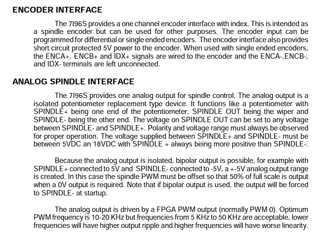
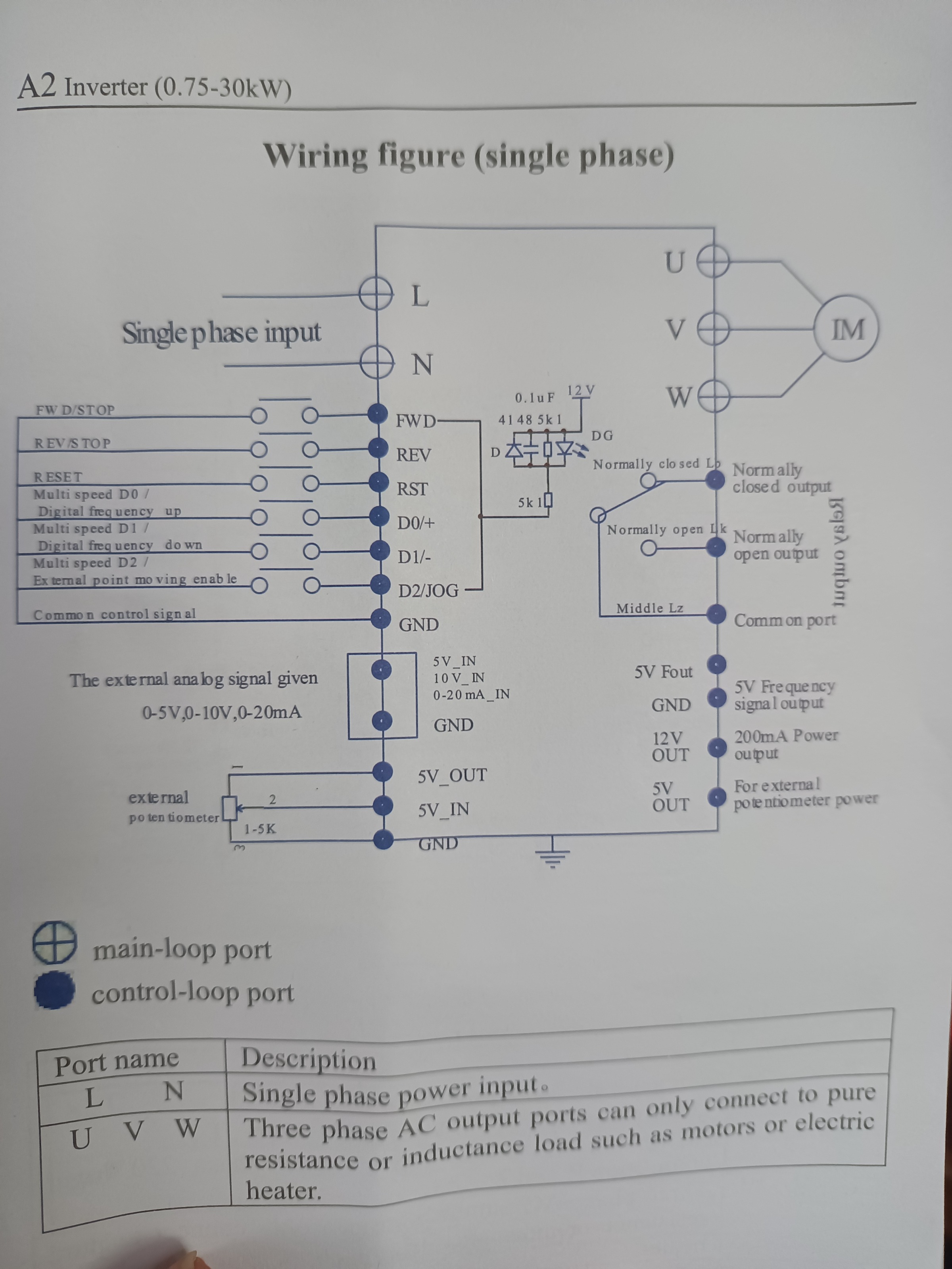
One more if thats ok.The Mesa 7i96s, has a spindle divider Spindle_out. Do you think it could be safely used with the to "5v_in" the spindle controller - manual attached.
One more if thats ok.The Mesa 7i96s, has a spindle divider Spindle_out. Do you think it could be safely used with the to "5v_in" the spindle controller - manual attached.
Attachments:
Please Log in or Create an account to join the conversation.
- PCW
-
- Offline
- Moderator
-
Less
More
- Posts: 17917
- Thank you received: 5246
27 Feb 2023 16:22 #265507
by PCW
Replied by PCW on topic Linux CNC - Mesa Card 7i96s with iHSV57-XX Servo Motor
Yes, the 7I96S analog spindle output is designed for potentiometer replacement:
7I96S SPINDLE- --> GND
7I96S SPINDLE OUT --> 5V_IN
7I96S SPINDLE+ --> --5V_OUT
7I96S SPINDLE- --> GND
7I96S SPINDLE OUT --> 5V_IN
7I96S SPINDLE+ --> --5V_OUT
Please Log in or Create an account to join the conversation.
- Drillbit
- Offline
- Junior Member
-
Less
More
- Posts: 24
- Thank you received: 3
09 Mar 2023 15:30 #266216
by Drillbit
Replied by Drillbit on topic Linux CNC - Mesa Card 7i96s with iHSV57-XX Servo Motor
Thank you.
Slow replying as one of the motors was bad and it took me ages to figure out.
Will implement the above.
Ok next question if thats ok.
I am just checking the steps on the y axis and with say a 1mm steps + and then the same steps backwards I get something like
0 - 0.99 - 1.99 - 2.98 etc. and then coming back I land on 0.23
I can then go forward again and get 0.99 - 1.99 etc. again.
So it looks like small but consistent backlash. The CNC is a Taige with ball screw.
I assume for the 0.99 I can adjust the steps per rotation.
I have not tuned anything. As the motor has a feedback counter I assume I can fine tune this with the settings in the motor but did not think that I could solve the backlash through motor configuration and that the backlash had to be a hardware fix (how?) or an adjustment in linuxCNC settings (how?)
Please Log in or Create an account to join the conversation.
- blazini36
- Offline
- Platinum Member
-

Less
More
- Posts: 972
- Thank you received: 167
11 Mar 2023 05:04 #266372
by blazini36
Replied by blazini36 on topic Linux CNC - Mesa Card 7i96s with iHSV57-XX Servo Motor
You should move a much larger amount than 1mm to calibrate the axis, like 20mm. And you must do so without changing direction or you introduce backlash which is a different problem. So if using a dial indicator move Y+ some amount, then 0 the indicator then move Y+ 20mm. if it did not move exactly 20mm than you adjust the STEP_SCALE in the .ini file or with the "Axis calibration tool". Repeat until you are happy with it.
After getting the STEP_SCALE set properly, then you work on backlash. Move Y+ some amount then with the 0 indicator, move Y- some defined amount, say 1mm. If it did not move 1mm the difference is your backlash. In the ini file under the Y axis add BACKLASH = 0.10 or whatever it was and this will enable backlash compensation for that axis. You should increase STEPGEN_MAXACCEL if using backlash comp.
After getting the STEP_SCALE set properly, then you work on backlash. Move Y+ some amount then with the 0 indicator, move Y- some defined amount, say 1mm. If it did not move 1mm the difference is your backlash. In the ini file under the Y axis add BACKLASH = 0.10 or whatever it was and this will enable backlash compensation for that axis. You should increase STEPGEN_MAXACCEL if using backlash comp.
The following user(s) said Thank You: Drillbit
Please Log in or Create an account to join the conversation.
- andypugh
-

- Offline
- Moderator
-
Less
More
- Posts: 19861
- Thank you received: 4636
13 Mar 2023 12:45 #266548
by andypugh
Replied by andypugh on topic Linux CNC - Mesa Card 7i96s with iHSV57-XX Servo Motor
I am not sure that I would trust a DTI over 20mm more than I would trust a ballscrew.
In my opinion the step scale should be based on the calculated leadscrew pitch and the gear ratios.
In my opinion the step scale should be based on the calculated leadscrew pitch and the gear ratios.
Please Log in or Create an account to join the conversation.
- blazini36
- Offline
- Platinum Member
-
Less
More
- Posts: 972
- Thank you received: 167
13 Mar 2023 15:40 #266561
by blazini36
Replied by blazini36 on topic Linux CNC - Mesa Card 7i96s with iHSV57-XX Servo Motor
Alright well in this guys particular case I don't think he's far off enough to have miscalculated and from his 2 movements he is coming up short 0.01mm/mm..........so what should he do?I am not sure that I would trust a DTI over 20mm more than I would trust a ballscrew.
In my opinion the step scale should be based on the calculated leadscrew pitch and the gear ratios.
Please Log in or Create an account to join the conversation.
- Drillbit
- Offline
- Junior Member
-
Less
More
- Posts: 24
- Thank you received: 3
15 Mar 2023 19:47 #266778
by Drillbit
Replied by Drillbit on topic Linux CNC - Mesa Card 7i96s with iHSV57-XX Servo Motor
0.01 over 20mm with a loss of 5 steps per 2.5mm out of 4000 steps..took a while but getting the hang of it. Backlash close to gone.
Just wanted to say thank you.
I think I can remove the 0.01 as well.
Just wanted to say thank you.
I think I can remove the 0.01 as well.
Please Log in or Create an account to join the conversation.
- rodw
-

- Offline
- Platinum Member
-
Less
More
- Posts: 11948
- Thank you received: 4068
15 Mar 2023 20:05 - 15 Mar 2023 20:05 #266781
by rodw
Replied by rodw on topic Linux CNC - Mesa Card 7i96s with iHSV57-XX Servo Motor
I'm not sure if you are on the right page. There should not be ANY lost steps. Lost steps only ocurr if a motor gets hot or you ask too much of it. Genrally Acceleration too high.
Listen to Andy.
Whit is your ball screw pitch (say its 5mm)
Is there any gearbox/belt reduction (say its 3:1)
What is your steps per rev (say its 200)
What is your microstepping. (say its 10 x)
So for our example above, the motor needs to turn 3 revs to travel 5mm.
Thats 3 x 200 x 10 steps per 5 mm = 6000
Your steps per mm = 6000/5 = 1200
Last edit: 15 Mar 2023 20:05 by rodw.
Please Log in or Create an account to join the conversation.
Time to create page: 0.408 seconds