1. Entirely plausible
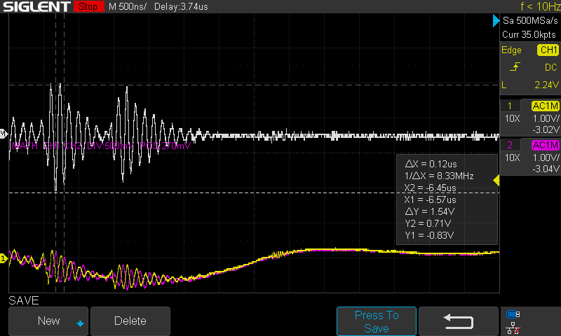
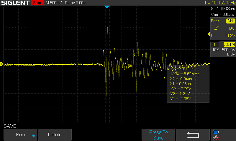
2. Yes. The point of those was to highlight the noise seen is very high frequency, and seemingly unlikely to cause steps
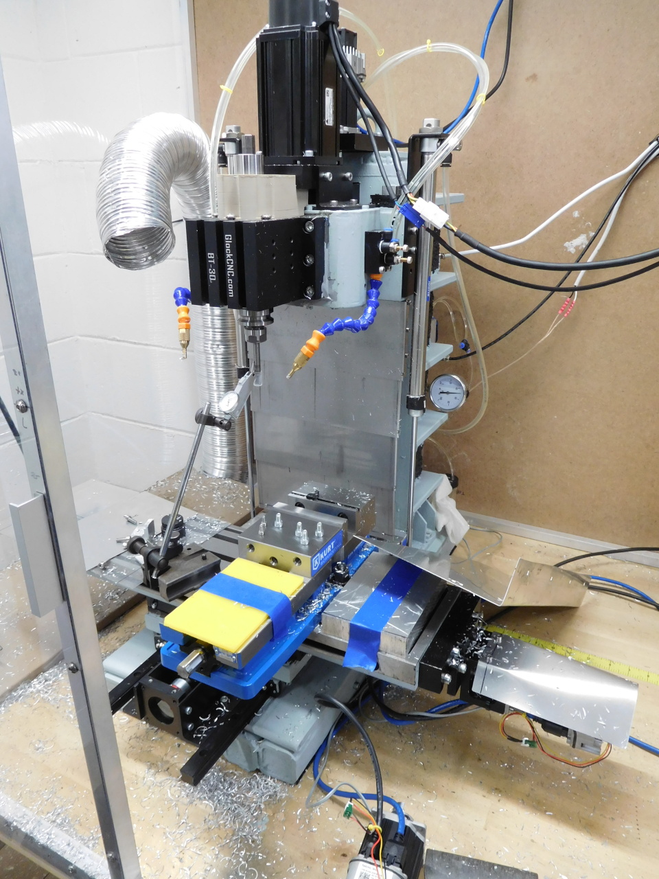
3. Spindle is a BT30 taper with a manual drawbar- no ATC/belleville washers/pull studs/etc. End mill is held in a Nikken SK10 collet holder torqued to 35~40 ft-lbs, which is the recommended value. Tools are changed with an impact driver on the drawbar.
4. I should definitely re-run the code and see if I can reproduce. Haven't wanted to spend the time/material doing so, but I've wasted enough other time on this to dwarf both costs. I'll rerun both with the same tools originally used and also with a different one. May or may not have time to do that today.
5. I put an indicator on the tool and pushed on it. I can get it to deflect ~0.0005 (5 tenths) before I don't really want to push on it any harder. Seems to apply going any direction.
6. So climb vs conventional? I've thought about this, but the pocket was roughed with an adaptive/HSM toolpath, which started in the center of the pocket- so the cutter is roughing -Y to +Y on the +X side of the pocket, and +Y to -Y on the -X side. Correct me if my logic is wrong here, but if cut direction were the problem, wouldn't you expect to see issues in (eg) the +X+Y and -X-Y quadrants instead of the -Y half?
Grounding: One ground loop snuck in (shielded cable with shield connected at both ends), though disconnecting that has no impact on noise I can see. Will fix it anyway.
Beyond that, I wouldn't rule ground issues out, but am not seeing an obvious issue. The entire cabinet is aluminum and grounded. It's not a single point due to eg the filters, PSUs, and spindle drive all grounding through their chassis. The axis motors have a completely isolated supply (transformer-based)- as far as they're concerned, the world is the isolated 65V and a couple opto-couplers. The 24V and 5V negatives are all tied to a single bus bar- which is NOT ground. A multimeter shows an open circuit between 24V negative and the enclosure. The machine body has no dedicated ground, but is grounded indirectly via the spindle motor. The axis motor bodies are electrically connected to the machine, but that's isolated from their power supply.
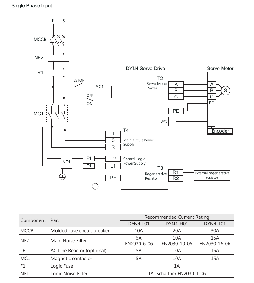
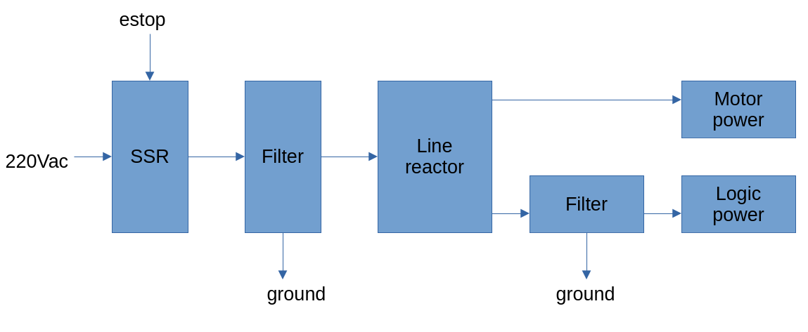
Spindle drive has all the recommended filtering. I deviated slightly from the recommendations by omitting fuses on the logic power, replacing the contactor with an SSR, and placing said SSR before all the filtering, though I don't see an issue with that. Pictures show datasheet drawing and the schematic of how my machine is wired.
Noise is much better when motors are disabled- got it on my to-do list to see what's the root causes there. Guess is the spindle drive, but need to verify. No ferrites on anything at the moment- and no mention of them in the DYN4 (spindle) nor ClearPath (axis) manuals. Not to say they wouldn't help, just that the manuals don't call them out as important. The PSUs are MeanWell units, so at least not no-name. SOP is to not buy dubious PSUs- they can cause too many problems and take out too much valuable hardware to be worth the risk. Not to mention noise, as you say.