Jones and shipley cylindrical grinder CNC conversion, grinding camshafts, cranks

More
1 year 11 months ago #315275 by timo
What I saw in hobby forums are mostly "copy" machines using a master(template)cam and some mechanical system to follow the template. (this boils down to 2d operation.

What do you mean by scale? Does it matter what size the parts are?

Please Log in or Create an account to join the conversation.

More
1 year 11 months ago #315280 by RotarySMP
Very cool project. Please post photos of the grinder when you get it.
The following user(s) said Thank You: smc.collins

Please Log in or Create an account to join the conversation.
More
1 year 11 months ago #315298 by smc.collins

timo post=315275 userid=29371What I saw in hobby forums are mostly "copy" machines using a master(template)cam and some mechanical system to follow the template. (this boils down to 2d operation.

What do you mean by scale? Does it matter what size the parts are?

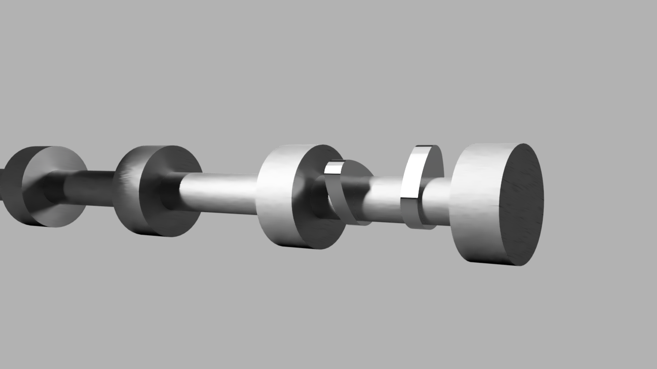
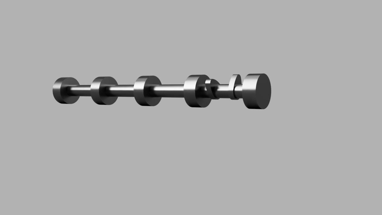
lobe shapes/profiles are not directly related to the base circle. That is to say that, the size of a lobe is correlated to the base diameter of the camshaft journal, but not always. I can upload some 3d models of camshafts and screen shots to illustrate this. 

Please Log in or Create an account to join the conversation.
More
1 year 11 months ago #315309 by spumco
Maybe an electronic 'copy' device to build up a library of lobe shapes?

I'm thinking of a motorized fixture to rotate the cam, with a high-res rotary encoder and a roller follower with a high-res linear encoder.  Rotate the cam and you can now plot the toolpath based on the follower location to rotational position (and follower wheel diameter)

Once in CAM, the plot should allow reverse engineering the lobe max lift and duration @0 or 0.050" lift since it should be obvious when the follower is riding on the cylindrical portion of the cam.

If the fixture were built with the follower on a track that's aligned with the camshaft long axis, it'd be easy to just work your way down each lobe without much setup time.

As for generating toolpaths, this looks like a good use of LCNC's external offsets.  Like everything, the details are probably fussy... but I think you could essentially load the plot back in to an external offset table and the 'X" axis would follow the rotary axis's rotation.  Multiple step-downs, of course, and I'm not sure how to avoid air cutting during the roughing phase.

Cool project.  Can't wait to see how it works out.
The following user(s) said Thank You: smc.collins

Please Log in or Create an account to join the conversation.

More
1 year 11 months ago - 1 year 11 months ago #315322 by smc.collins
I have actually found 4 companies that make software, 1 of them is relatively affordable. The issue again becomes generating tools path. I am curious about the Freecad work offset bench however. does freecad support 4th axis or C axis work ? I was considering adding a indicator with a radius foot that could act as a encoder onto a set of centers I have laying around with a encoder to grab the pertinent data. Very open to ideas on all of this BTW. the air cutting issue isn\t that big of a deal. If I can figure out how to generate the roughing profiles on the C axis, I can add a spindle to my lathe, rough turn the camshaft and then rough in the cam lobes. Stand it up and drill the ends or do it as a C-axis drilling open for the locating pin or bolt up.

I am very open to suggestions on all of this BTW  
Last edit: 1 year 11 months ago by smc.collins.

Please Log in or Create an account to join the conversation.

More
1 year 11 months ago #315330 by spumco
I'd think you'd want to put the gear holes, and especially the registration hole(s), in the end before you start grinding lobes.  Even with adjustable timing pulley/gears you still need all the lobes to be referenced to something.

Do you have a good workhead for your grinder?  I picked up a surplus high-end grinder work spindle that I was thinking of turning in to a lathe headstock, but that's not likley to happen as it has no through-bore.  I could make you a sweet deal on it... quad AC bearings and runout is not measurable on a 50-millionths indicator.
The following user(s) said Thank You: smc.collins

Please Log in or Create an account to join the conversation.

Time to create page: 0.205 seconds
Powered by Kunena Forum