These are some great questions. I spent some time collecting information to address them.
cakeslob question: I ran the 1"-8 scratch threads again. I tried hand turning the spindle, then ran it at 100, 150, and 200 RPM. I found the following:
1) Yes, you can run the threading G-code and cut the thread by turning the spindle by hand
2) The hand turned scratch wobbles a bit compared to the ones at set speeds
3) The hand turned scratch is the leftmost one in the photo, then the 100 RPM to its right, then the 150 and the rightmost thread at 200 RPM.
4) The spacing of the scratches, measured as best as I can from the hand turned scratch line, is
a) 0-100RPM -0.025"
b) 0-150 RPM -0.055"
c) 0-200 RPM -0.085"
This supports andypugh's comment about the Y axis having to catch up the position after it detects the index pulse. The faster the speed, the more the thread falls behind the desired position.
PCW question:
I've attached my INI and HAL files.
Here's the section for the Z axis
Code:
#********************
# Axis Z
#********************
[AXIS_Z]
MIN_LIMIT = 0.001
MAX_LIMIT = 19.5
MAX_VELOCITY = 1.8
MAX_ACCELERATION = 2.0
[JOINT_1]
TYPE = LINEAR
HOME_SEARCH_VEL = 0.8
# overshoot switch if too high
HOME_LATCH_VEL = 0.1
#HOME_FINAL_VEL = 1.0
HOME_IGNORE_LIMITS = YES
HOME_USE_INDEX = NO
HOME_OFFSET = 19.95
HOME = 9
HOME_IS_SHARED = 1
HOME_SEQUENCE = 0
VOLATILE_HOME = 1
# STARTING VALUES FERROR 0.001 0.0005
FERROR = 0.01
MIN_FERROR = 0.001
# MAX_VELOCITY = STEPGEN_MAXVEL / 1.25. STEPGEN_MAXVEL = experimental maximum
# If BACKLASH is not set:
# MAX_ACCELERATION = STEPGEN_MAXACCEL / 1.25. STEPGEN_MAXACCEL = MAX_ACCELERATION * 2.5
# If BACKLASH is set:
# MAX_ACCELERATION = experimental maximum acceleration / 1.25. STEPGEN_MAXACCEL = MAX_ACCELERATION * 2.5
# STARTING VALUES FERROR 1.8 2.25 2.5 3.2
MAX_VELOCITY = 1.8
MAX_ACCELERATION = 2.0
# These should match values above in [AXIS_Z]
STEPGEN_MAXVEL = 2.5
# If set too low, STEPGEN_MAXACCEL will cause massive joint follow errors!
STEPGEN_MAXACCEL = 5.0
P = 1000.0
I = 0.0
D = 0.0
FF0 = 0.0
FF1 = 1.0
FF2 = 0.0
BIAS = 0.0
DEADBAND = 0.0
MAX_OUTPUT = 0
# these are in nanoseconds
DIRSETUP = 100000
DIRHOLD = 100000
STEPLEN = 2000
STEPSPACE = 2000
STEP_SCALE = 12825.0
MIN_LIMIT = 0.001
MAX_LIMIT = 19.5
BACKLASH = 0.008
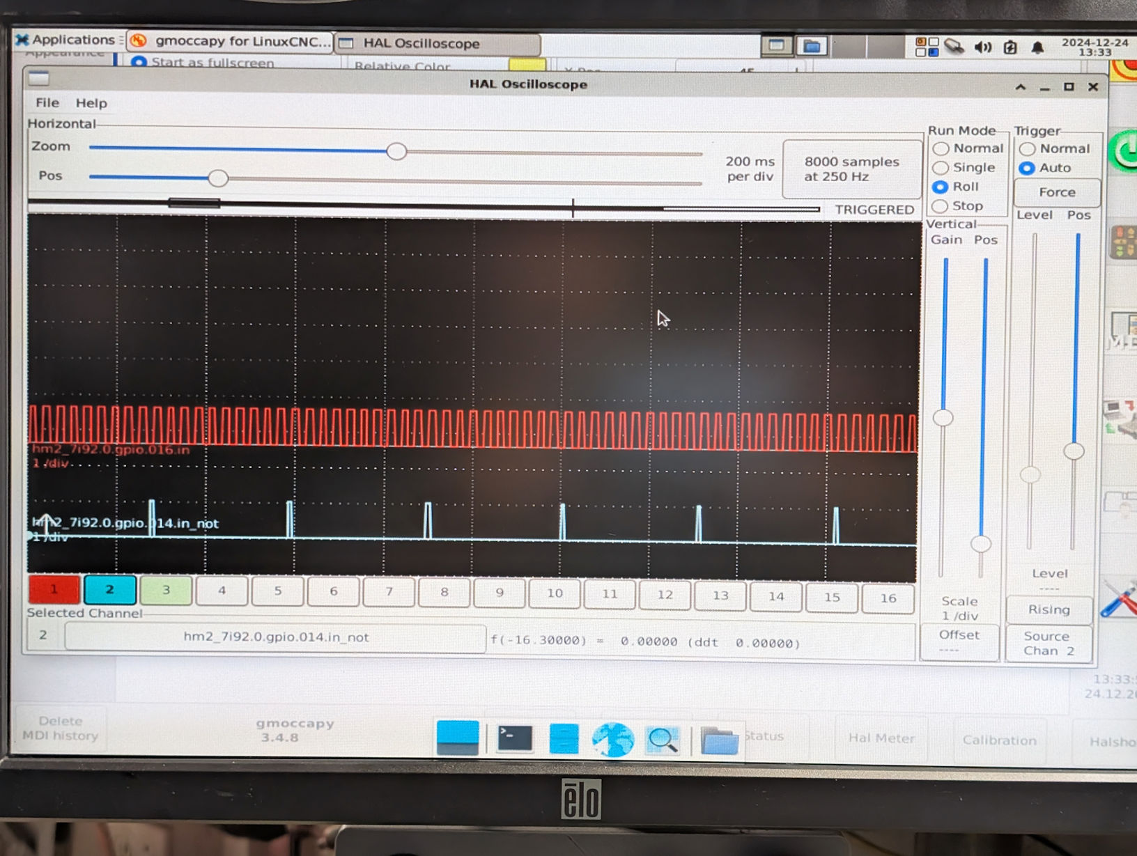
I used HALSCOPE and watched hm2_7i92.0.gpio.014.in_not (spindle index) and hm2_7i92.0.gpio.016.in (spindle A). That was working as expected, as I got one index pulse per 10 "A" pulses.
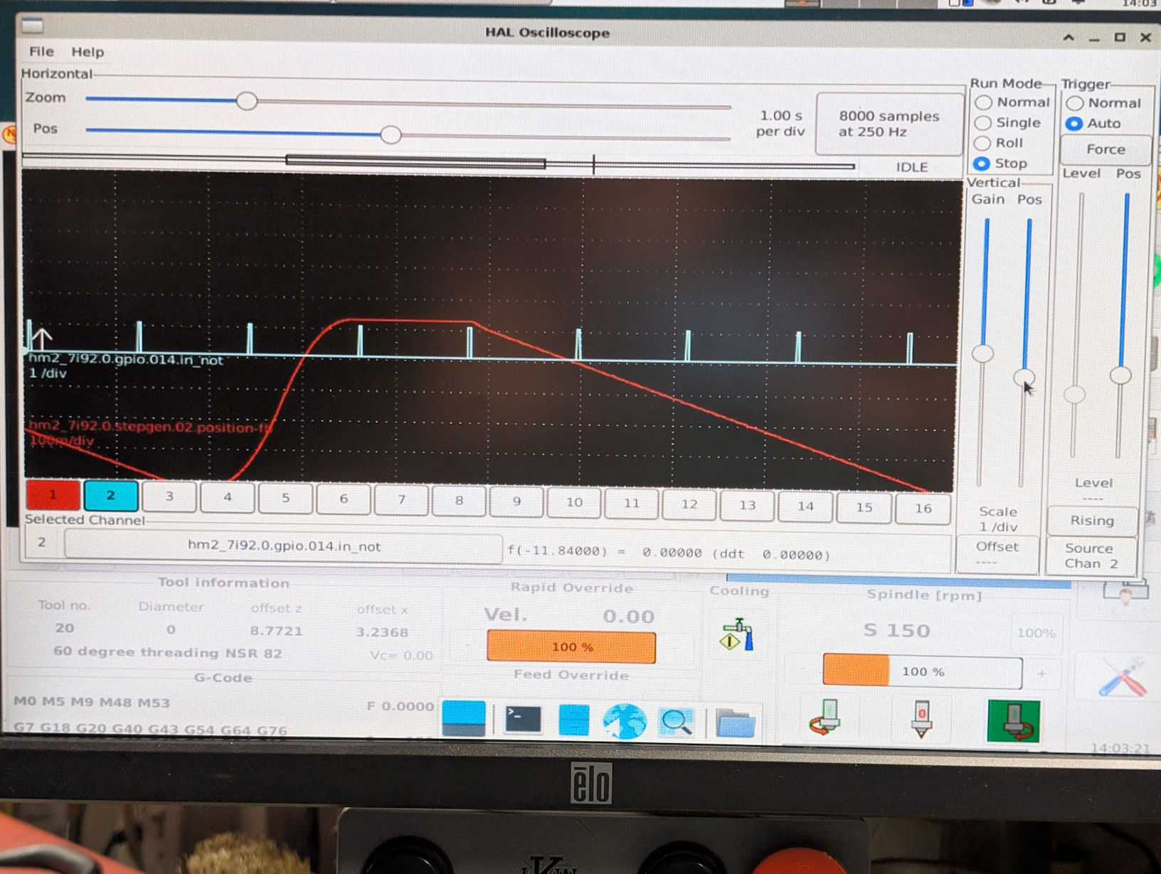
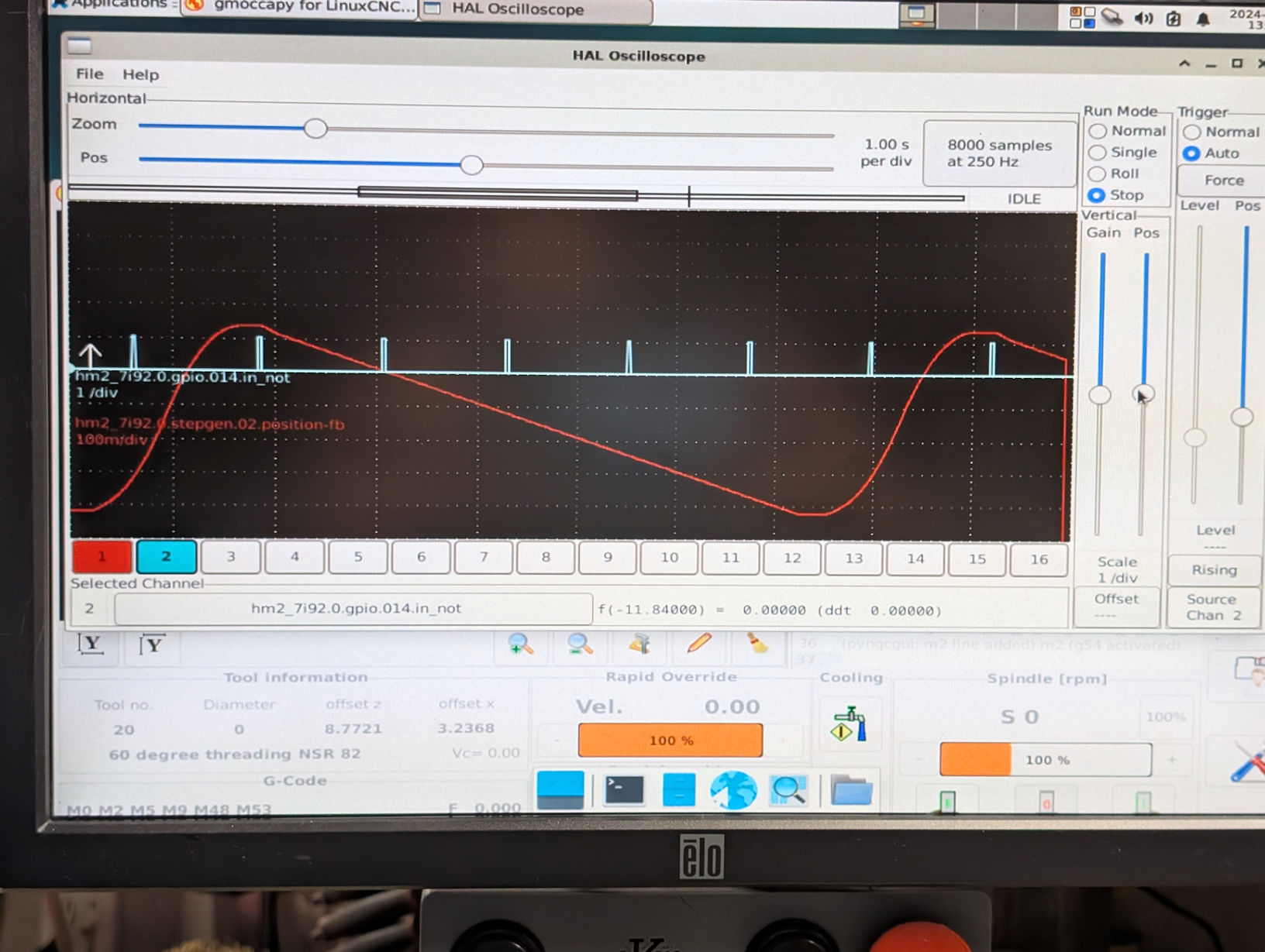
I then watched the spindle index and hm2_7i92.0.stepgen.02.position-1b (Z axis position) while running the threading program.
For 100 RPM:
For 200 RPM:
This looks to me like it's working as expected, where the falling index pulse begins the carriage Z movement. Note that I have steppers and this is not a real feedback signal on the position..That leads me to believe that LincxCNC is working correctly and that my problem is a physical one with my lathe.
M4MazakUser question:
Yes, both the index and "A" spindle signals are driven directly off the spindle.
andypugh question:
I'm using the threading program from the O-code section of the forum (and which I wrote). Before issuing the G76 code, the program moves the tool to the starting X and Z position. I think that there's validity to your comment about the axis acceleration perhaps affecting the spindle synch point. I'm not sure what to do about it, though. The carriage on my lathe probably weighs nearly 100 lbs, and the stepper motor is probably undersized. I've had to limit my Z acceleration to 2 i/s^2, or it loses steps.
I ran the calcs you suggested (v = sqrt(2as)) for the 8 tpi thread I'm trying to cut. For the final velocity, I need to cut 1/8" per revolution at the set RPM.
For 100 RPM, v = 100 r/m / 60 s/m / 8 r/i = 0.208 i/s
And the distance to reach that speed s = v^2 / 2a, or 0.208^2 / (2 * 2) = 0.011"
For 200 RPM, s = 0.043"
The takeaway here is that the calculated distance is exponential with speed. When I measured the scratch marks from the hand turned (very slow RPM) values I got 0-100 RPM was 0.25" and 0-200 RPM was 0.085", which is exponential behavior. They're also about twice the values calculated in the formula.
So, I'm still not sure there's a path forward to correct this. A larger stepper, able to accelerate the heavy carriage would likely help, in that I could increase the maximum acceleration. But I'm not losing steps, so the program should be able to handle this. Perhaps a servo motor with closed loop control would fix it.