- LinuxCNC
- General LinuxCNC Questions
- Axis position shift during helical boring - Fusion 360 Personal + Mesa 7i96s + C
Axis position shift during helical boring - Fusion 360 Personal + Mesa 7i96s + C
- maruf1777
- Offline
- New Member
-

Less
More
- Posts: 11
- Thank you received: 0
16 Mar 2026 19:57 - 16 Mar 2026 20:01 #344364
by maruf1777
Axis position shift during helical boring - Fusion 360 Personal + Mesa 7i96s + C was created by maruf1777
Hi everyone,
I'm experiencing cumulative axis position shifts (mostly Y, some X) during helical boring operations generated by Fusion 360 Personal Use. The shift happens between passes, not during cutting. I've done extensive testing to isolate the cause and I'm stuck — hoping someone with trajectory planner experience can help.
HARDWARE:
- 3-axis mill, 1204 ballscrews
- Mesa 7i96s ethernet card
- Teknic ClearPath CPM-SDSK-2311S-RQN servos (step/dir mode)
- 75VDC PSU
- Raspberry Pi 5 running Debian Bookworm
- LinuxCNC Master (2.9)
THE PROBLEM:
When running a Fusion 360 helical bore operation (3 passes: rough, semi-finish, finish), the machine shifts position during the helical arc cutting itself. The first boring pass starts correctly, but position drifts during the operation. The shift is cumulative across passes — each subsequent pass is worse. I initially thought the shift was only happening between passes during repositioning, but after extensive testing I've confirmed it also occurs during the actual G3 helical arc execution.
WHAT I'VE RULED OUT:
1. NOT mechanical: Dial indicator shows <0.01mm backlash. Coupling and ballscrew are tight.
2. NOT motor faults: ClearPath LEDs stay green, no faults. (Note: HLFB is wired but not yet configured in HAL — this is on my to-do list.)
3. NOT lost steps during linear moves: I wrote a test program doing 20 cycles of G91 G1 Y50 F1000 / G1 Y-50 and Y returns perfectly. Zero shift.
4. NOT electrical noise / VFD: Shift occurs with VFD off, spindle off, no tool, air cutting only.
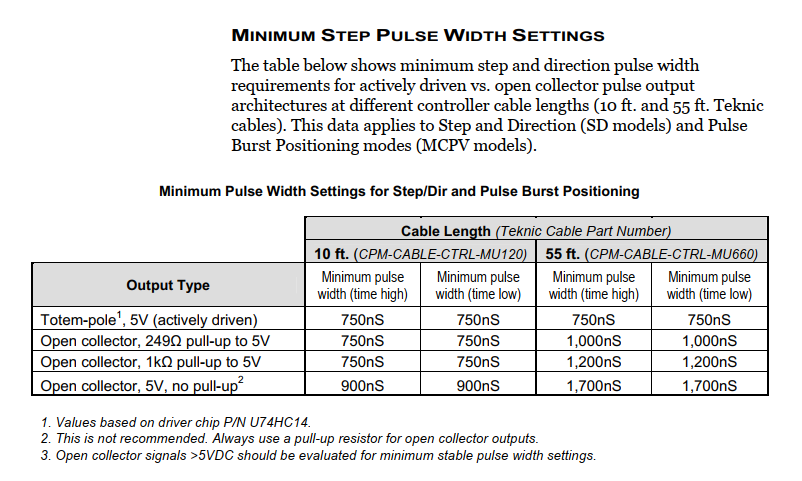
5. NOT step timing: Tested DIRSETUP/DIRHOLD at 2000, 5000, and 10000ns. 5000 was slightly better but didn't solve it.
WHAT I'VE FOUND:
The problem appears related to how the trajectory planner handles the G-code Fusion 360 Personal generates. Key factors:
A) Fusion 360 Personal Use converts ALL G0 rapids to G1 moves. This means repositioning between bore passes (retract, XY travel, approach) are G1 moves subject to G64 path blending. The machine blends through the repositioning corners instead of making exact stops.
") The bore operation uses helical arcs (G3 in XY with simultaneous Z) — this is the exact pattern described in GitHub Issue #426 (Arc Blending Bug).
The bore operation uses helical arcs (G3 in XY with simultaneous Z) — this is the exact pattern described in GitHub Issue #426 (Arc Blending Bug).
C) I tested ARC_BLEND tuning parameters:
ARC_BLEND_ENABLE = 1
ARC_BLEND_FALLBACK_ENABLE = 1
ARC_BLEND_OPTIMIZATION_DEPTH = 50
ARC_BLEND_GAP_CYCLES = 4
ARC_BLEND_RAMP_FREQ = 100
D) ARC_BLEND_ENABLE = 0 did NOT fix the second file either.
G-CODE STRUCTURE:
The problematic repositioning sequence between bore passes (02.ngc):
N635 G1 X-77.844 Y12.6 (exit move)
N645 Z5. (retract - G1, should be G0)
N650 Z15. (retract more - G1, should be G0)
N655 Z4. (approach - G1, should be G0)
N660 Z2. (approach to cut depth - G1)
N665 X-80.544 Y13.2 (XY reposition AT cut depth - G1, gets blended!)
N670 G3 X-81.144 Y12.6 ... (arc cutting begins)
My INI Snippet:
[EMCMOT]
EMCMOT = motmod
SERVO_PERIOD = 1000000
ARC_BLEND_ENABLE = 1
ARC_BLEND_FALLBACK_ENABLE = 1
ARC_BLEND_OPTIMIZATION_DEPTH = 50
ARC_BLEND_GAP_CYCLES = 4
ARC_BLEND_RAMP_FREQ = 100
[JOINT_0] (X)
MAX_VELOCITY = 50
MAX_ACCELERATION = 150
STEPGEN_MAXVEL = 62.5
STEPGEN_MAXACCEL = 250.0
DIRSETUP = 5000
DIRHOLD = 5000
STEP_SCALE = 200.100
[JOINT_1] (Y)
MAX_VELOCITY = 50
MAX_ACCELERATION = 150
STEPGEN_MAXVEL = 62.5
STEPGEN_MAXACCEL = 250.00
DIRSETUP = 5000
DIRHOLD = 5000
STEP_SCALE = 200.460
G-code preamble: G64 P0.005 Q0.005
QUESTIONS:
1. Is there a known interaction between Fusion 360 Personal's G1-only rapids and the trajectory planner's arc blending that could cause multi-millimeter position shifts?
2. Is there a recommended set of ARC_BLEND parameters for helical boring operations where G1 repositioning is mixed with G3 arcs?
3. Would modifying the linuxcnc.cps post processor to insert G61 before repositioning moves and G64 before cutting moves be the correct approach?
4. Should I be looking at something else entirely?
I can attach the G-code files if helpful. Any guidance appreciated — I've been chasing this for a while.
Thanks!
I'm experiencing cumulative axis position shifts (mostly Y, some X) during helical boring operations generated by Fusion 360 Personal Use. The shift happens between passes, not during cutting. I've done extensive testing to isolate the cause and I'm stuck — hoping someone with trajectory planner experience can help.
HARDWARE:
- 3-axis mill, 1204 ballscrews
- Mesa 7i96s ethernet card
- Teknic ClearPath CPM-SDSK-2311S-RQN servos (step/dir mode)
- 75VDC PSU
- Raspberry Pi 5 running Debian Bookworm
- LinuxCNC Master (2.9)
THE PROBLEM:
When running a Fusion 360 helical bore operation (3 passes: rough, semi-finish, finish), the machine shifts position during the helical arc cutting itself. The first boring pass starts correctly, but position drifts during the operation. The shift is cumulative across passes — each subsequent pass is worse. I initially thought the shift was only happening between passes during repositioning, but after extensive testing I've confirmed it also occurs during the actual G3 helical arc execution.
WHAT I'VE RULED OUT:
1. NOT mechanical: Dial indicator shows <0.01mm backlash. Coupling and ballscrew are tight.
2. NOT motor faults: ClearPath LEDs stay green, no faults. (Note: HLFB is wired but not yet configured in HAL — this is on my to-do list.)
3. NOT lost steps during linear moves: I wrote a test program doing 20 cycles of G91 G1 Y50 F1000 / G1 Y-50 and Y returns perfectly. Zero shift.
4. NOT electrical noise / VFD: Shift occurs with VFD off, spindle off, no tool, air cutting only.
5. NOT step timing: Tested DIRSETUP/DIRHOLD at 2000, 5000, and 10000ns. 5000 was slightly better but didn't solve it.
WHAT I'VE FOUND:
The problem appears related to how the trajectory planner handles the G-code Fusion 360 Personal generates. Key factors:
A) Fusion 360 Personal Use converts ALL G0 rapids to G1 moves. This means repositioning between bore passes (retract, XY travel, approach) are G1 moves subject to G64 path blending. The machine blends through the repositioning corners instead of making exact stops.
The bore operation uses helical arcs (G3 in XY with simultaneous Z) — this is the exact pattern described in GitHub Issue #426 (Arc Blending Bug).C) I tested ARC_BLEND tuning parameters:
ARC_BLEND_ENABLE = 1
ARC_BLEND_FALLBACK_ENABLE = 1
ARC_BLEND_OPTIMIZATION_DEPTH = 50
ARC_BLEND_GAP_CYCLES = 4
ARC_BLEND_RAMP_FREQ = 100
D) ARC_BLEND_ENABLE = 0 did NOT fix the second file either.
G-CODE STRUCTURE:
The problematic repositioning sequence between bore passes (02.ngc):
N635 G1 X-77.844 Y12.6 (exit move)
N645 Z5. (retract - G1, should be G0)
N650 Z15. (retract more - G1, should be G0)
N655 Z4. (approach - G1, should be G0)
N660 Z2. (approach to cut depth - G1)
N665 X-80.544 Y13.2 (XY reposition AT cut depth - G1, gets blended!)
N670 G3 X-81.144 Y12.6 ... (arc cutting begins)
My INI Snippet:
[EMCMOT]
EMCMOT = motmod
SERVO_PERIOD = 1000000
ARC_BLEND_ENABLE = 1
ARC_BLEND_FALLBACK_ENABLE = 1
ARC_BLEND_OPTIMIZATION_DEPTH = 50
ARC_BLEND_GAP_CYCLES = 4
ARC_BLEND_RAMP_FREQ = 100
[JOINT_0] (X)
MAX_VELOCITY = 50
MAX_ACCELERATION = 150
STEPGEN_MAXVEL = 62.5
STEPGEN_MAXACCEL = 250.0
DIRSETUP = 5000
DIRHOLD = 5000
STEP_SCALE = 200.100
[JOINT_1] (Y)
MAX_VELOCITY = 50
MAX_ACCELERATION = 150
STEPGEN_MAXVEL = 62.5
STEPGEN_MAXACCEL = 250.00
DIRSETUP = 5000
DIRHOLD = 5000
STEP_SCALE = 200.460
G-code preamble: G64 P0.005 Q0.005
QUESTIONS:
1. Is there a known interaction between Fusion 360 Personal's G1-only rapids and the trajectory planner's arc blending that could cause multi-millimeter position shifts?
2. Is there a recommended set of ARC_BLEND parameters for helical boring operations where G1 repositioning is mixed with G3 arcs?
3. Would modifying the linuxcnc.cps post processor to insert G61 before repositioning moves and G64 before cutting moves be the correct approach?
4. Should I be looking at something else entirely?
I can attach the G-code files if helpful. Any guidance appreciated — I've been chasing this for a while.
Thanks!
Last edit: 16 Mar 2026 20:01 by maruf1777. Reason: Wrong Syntax
Please Log in or Create an account to join the conversation.
- PCW
-

- Offline
- Moderator
-

Less
More
- Posts: 17917
- Thank you received: 5246
16 Mar 2026 22:23 #344374
by PCW
Replied by PCW on topic Axis position shift during helical boring - Fusion 360 Personal + Mesa 7i96s + C
5. NOT step timing: Tested DIRSETUP/DIRHOLD at 2000, 5000, and 10000ns. 5000 was slightly better but didn't solve it.
If changing the step timing changes anything that suggests that something is marginal
electrically or timing wise
Have you tried doubling the step time?
Are the drives step/dir connections single ended or differential? (single ended is suggested for opto-coupled inputs)
Does the DRO show the error? if not it's most likely not the Trajectory Planner
The following user(s) said Thank You: tommylight, maruf1777
Please Log in or Create an account to join the conversation.
- maruf1777
- Offline
- New Member
-
Less
More
- Posts: 11
- Thank you received: 0
17 Mar 2026 13:55 #344409
by maruf1777
Replied by maruf1777 on topic Axis position shift during helical boring - Fusion 360 Personal + Mesa 7i96s + C
DRO shows the error. Probing the same physical reference point before and after the program gives Y 51.252 before and Y 48.583 after — a 2.67mm shift. HLFB is configured in ASG In-Range mode with 20 count threshold and did NOT trigger during the operation. This confirms the motor followed the commanded path accurately — the error is in what LinuxCNC is commanding, not in the motor execution.
Please Log in or Create an account to join the conversation.
- spumco
- Offline
- Platinum Member
-

Less
More
- Posts: 2107
- Thank you received: 874
17 Mar 2026 14:31 #344412
by spumco
Clearpath brushless servos use single-ended opto-coupled inputs. The 'drives' are built in to the motors - there's no separate drive, and they're powered by (up to) 75VDC.
Replied by spumco on topic Axis position shift during helical boring - Fusion 360 Personal + Mesa 7i96s + C
Are the drives step/dir connections single ended or differential? (single ended is suggested for opto-coupled inputs)
Clearpath brushless servos use single-ended opto-coupled inputs. The 'drives' are built in to the motors - there's no separate drive, and they're powered by (up to) 75VDC.
Please Log in or Create an account to join the conversation.
- maruf1777
- Offline
- New Member
-
Less
More
- Posts: 11
- Thank you received: 0
17 Mar 2026 15:29 #344415
by maruf1777
Replied by maruf1777 on topic Axis position shift during helical boring - Fusion 360 Personal + Mesa 7i96s + C
Indeed I Did Wired it
TB1 Pin7 Input A-, B-
TB1 Pin5 Input A+
TB1 Pin3 Input B+
TB1 Pin7 Input A-, B-
TB1 Pin5 Input A+
TB1 Pin3 Input B+
Please Log in or Create an account to join the conversation.
- maruf1777
- Offline
- New Member
-
Less
More
- Posts: 11
- Thank you received: 0
17 Mar 2026 15:34 - 17 Mar 2026 15:37 #344416
by maruf1777
Replied by maruf1777 on topic Axis position shift during helical boring - Fusion 360 Personal + Mesa 7i96s + C
DRO shows identical position at arc entry and exit — LinuxCNC believes the machine returned to the correct point. But probing a fixed reference shows X shifted +9.3mm and Y shifted -12.2mm. HLFB is configured at 20 counts and did NOT trigger. This means every commanded step was executed by the motor. The error is in the arc interpolation — the step path LinuxCNC generates to trace the circular arcs does not sum back to the correct physical position.
LinuxCNC version: Master (2.9), running on Raspberry Pi 5 (4GB), Debian Bookworm, Mesa 7i96s over ethernet (hm2_eth), SERVO_PERIOD = 1000000.
LinuxCNC version: Master (2.9), running on Raspberry Pi 5 (4GB), Debian Bookworm, Mesa 7i96s over ethernet (hm2_eth), SERVO_PERIOD = 1000000.
Last edit: 17 Mar 2026 15:37 by maruf1777. Reason: Addon
Please Log in or Create an account to join the conversation.
- hmnijp
- Offline
- Senior Member
-

Less
More
- Posts: 42
- Thank you received: 49
17 Mar 2026 18:37 - 17 Mar 2026 18:39 #344425
by hmnijp
Linuxcnc doesn't generate a step signal. All planner calculations are based on position (float64 number) and velocity signals.These numbers (not steps or pulses) for each servo cycle are sent to the Mesa board, where "stepgens" converts them into pulses.
These are the connections in hal:
joint.N.pos-cmd -> hm2.N.stepgen.position-cmd;
Each cycle, Mesa sends back the counted number of generated pulses for reporting:
joint.N.pos-fb <- hm2.N.stepgen.position-fb;
The difference between the sent position and the feedback is tracked using the joint.N.f-error pin.The path planner (on the computer) and stepgen (inside the Mesa board) do not influence each other, but each performs its own role in the chain.
I hope you understand that, in this logic, the position can't simply shift in the planner. If there was an error, it would mean it was transmitting an incorrect coordinate to the mesa, and the same incorrect coordinate would be visible in your DRO (since it's also connected to the joint.N.pos-cmd == axis.N.pos-cmd signal). And the incorrect path would be drawn in the graphics window. The "live plot" draws either based on the pos-cmd or pos-fb numbers. there's a switch for this.
If "LinuxCNC believes the machine has returned to the correct point," then the planner has indeed returned to that point and is transmitting that exact position command to mesa.If the error occurred in stepgen inside mesa, then the position-fb counter would have returned an incorrect number of counts (as a float64 number, not pulses).
If your servos don't report their own following error, then there remains the possibility of an error between Mesa => Servo. Due to electrical interference/noise, not all pulses could have been received by your servo - it thinks it's following the path, but in fact, not all the pulses reached it.
This is confirmed by the fact that you saw a connection between the error and pulse timings.
I have been working with linuxcnc and fusion 360 for a long time as post programmer, so I can assure you - there is no connection between the post processor, pathplanner and your problem. Both work fine.
Replied by hmnijp on topic Axis position shift during helical boring - Fusion 360 Personal + Mesa 7i96s + C
DRO shows identical position at arc entry and exit — LinuxCNC believes the machine returned to the correct point. But probing a fixed reference shows X shifted +9.3mm and Y shifted -12.2mm. HLFB is configured at 20 counts and did NOT trigger. This means every commanded step was executed by the motor. The error is in the arc interpolation — the step path LinuxCNC generates to trace the circular arcs does not sum back to the correct physical position.
LinuxCNC version: Master (2.9), running on Raspberry Pi 5 (4GB), Debian Bookworm, Mesa 7i96s over ethernet (hm2_eth), SERVO_PERIOD = 1000000.
Linuxcnc doesn't generate a step signal. All planner calculations are based on position (float64 number) and velocity signals.These numbers (not steps or pulses) for each servo cycle are sent to the Mesa board, where "stepgens" converts them into pulses.
These are the connections in hal:
joint.N.pos-cmd -> hm2.N.stepgen.position-cmd;
Each cycle, Mesa sends back the counted number of generated pulses for reporting:
joint.N.pos-fb <- hm2.N.stepgen.position-fb;
The difference between the sent position and the feedback is tracked using the joint.N.f-error pin.The path planner (on the computer) and stepgen (inside the Mesa board) do not influence each other, but each performs its own role in the chain.
I hope you understand that, in this logic, the position can't simply shift in the planner. If there was an error, it would mean it was transmitting an incorrect coordinate to the mesa, and the same incorrect coordinate would be visible in your DRO (since it's also connected to the joint.N.pos-cmd == axis.N.pos-cmd signal). And the incorrect path would be drawn in the graphics window. The "live plot" draws either based on the pos-cmd or pos-fb numbers. there's a switch for this.
If "LinuxCNC believes the machine has returned to the correct point," then the planner has indeed returned to that point and is transmitting that exact position command to mesa.If the error occurred in stepgen inside mesa, then the position-fb counter would have returned an incorrect number of counts (as a float64 number, not pulses).
If your servos don't report their own following error, then there remains the possibility of an error between Mesa => Servo. Due to electrical interference/noise, not all pulses could have been received by your servo - it thinks it's following the path, but in fact, not all the pulses reached it.
This is confirmed by the fact that you saw a connection between the error and pulse timings.
I have been working with linuxcnc and fusion 360 for a long time as post programmer, so I can assure you - there is no connection between the post processor, pathplanner and your problem. Both work fine.
Last edit: 17 Mar 2026 18:39 by hmnijp.
The following user(s) said Thank You: tommylight
Please Log in or Create an account to join the conversation.
- tommylight
-

- Away
- Moderator
-
Less
More
- Posts: 21631
- Thank you received: 7386
17 Mar 2026 21:24 #344432
by tommylight
And that goes both directions, so the actual error can hypothetically be 39 counts without triggering.
Granted, i agree with others, interference is the first thing t eliminate as you do have cumulative errors on both axis, and probably the third, too.
Replied by tommylight on topic Axis position shift during helical boring - Fusion 360 Personal + Mesa 7i96s + C
How much is that in distance?HLFB is configured at 20 counts and did NOT trigger.
And that goes both directions, so the actual error can hypothetically be 39 counts without triggering.
Granted, i agree with others, interference is the first thing t eliminate as you do have cumulative errors on both axis, and probably the third, too.
Please Log in or Create an account to join the conversation.
- PCW
-
- Offline
- Moderator
-
Less
More
- Posts: 17917
- Thank you received: 5246
17 Mar 2026 22:23 #344437
by PCW
Replied by PCW on topic Axis position shift during helical boring - Fusion 360 Personal + Mesa 7i96s + C
I would also try:
1. Single ended step/dir wiring:
7I96S +5V --> MOTOR STEP+
7I96S STEP- --> MOTOR STEP-
7I96S +5V --> MOTOR DIR+
7I96S STEP- --> MOTOR DIR-
2. Increase the step length (double if possible)
1. Single ended step/dir wiring:
7I96S +5V --> MOTOR STEP+
7I96S STEP- --> MOTOR STEP-
7I96S +5V --> MOTOR DIR+
7I96S STEP- --> MOTOR DIR-
2. Increase the step length (double if possible)
Please Log in or Create an account to join the conversation.
- spumco
- Offline
- Platinum Member
-
Less
More
- Posts: 2107
- Thank you received: 874
18 Mar 2026 00:26 #344441
by spumco
The standard encoder for Clearpath is 800 counts/rev. With 4mm pitch screws that's about +/- 20 microns before the servo vomits.
OP...
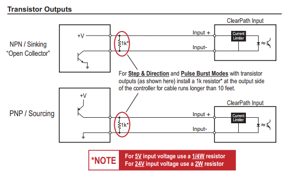
I've had issues with clearpath step/dir that were resolved using the resistor they indicate in the user manual. Your cables may not be very long (mine were ~20 feet), but it did help with lost pulses from the PLC to the motor.
Note that I never had an issue with direction changes, only the motors not moving as far as I'd expected. I chased couplings, planetary reducer shaft clamps, and everything mechanical until I put the resistors in.
Also, Clearpath has an input filtering setting in MSP software; might want to play with that if you think some of the pulses are going astray.
Replied by spumco on topic Axis position shift during helical boring - Fusion 360 Personal + Mesa 7i96s + C
Tommy...
How much is that in distance?
The standard encoder for Clearpath is 800 counts/rev. With 4mm pitch screws that's about +/- 20 microns before the servo vomits.
OP...
I've had issues with clearpath step/dir that were resolved using the resistor they indicate in the user manual. Your cables may not be very long (mine were ~20 feet), but it did help with lost pulses from the PLC to the motor.
Note that I never had an issue with direction changes, only the motors not moving as far as I'd expected. I chased couplings, planetary reducer shaft clamps, and everything mechanical until I put the resistors in.
Also, Clearpath has an input filtering setting in MSP software; might want to play with that if you think some of the pulses are going astray.
Attachments:
Please Log in or Create an account to join the conversation.
- LinuxCNC
- General LinuxCNC Questions
- Axis position shift during helical boring - Fusion 360 Personal + Mesa 7i96s + C
Time to create page: 0.172 seconds