5i25+7i76 Spindle control issue
- johnjsb
- Offline
- New Member
-

Less
More
- Posts: 18
- Thank you received: 0
22 Aug 2013 00:13 #37935
by johnjsb
5i25+7i76 Spindle control issue was created by johnjsb
I can't seem to get the spindle working after a few days of wondering around the net. I had to jumper the enable pin on the spindle controller and the direction doesn't work. when i issue a m3 it turns clockwise looking from top of spindle(correct cutting direction). when i input m4 spindle stops with 0v on tb4-pin2. either m3 or m4 gives 5v on spindle_ena+ pin6 (which needs to be ground) and 5v on spindle-dir+ pin8(which needs to be 0v for ccw m4). m3 with s5000 gives me 9.07v at 5000rpm so thats good. Please help i think there needs to be more code here with some kind of -not or -invert somewhere.
here is my hal file:
here is my .ini as well:
here is my hal file:
# Generated by PNCconf at Tue Aug 20 18:17:20 2013
# If you make changes to this file, they will be
# overwritten when you run PNCconf again

loadrt trivkins
loadrt [EMCMOT]EMCMOT servo_period_nsec=[EMCMOT]SERVO_PERIOD num_joints=[TRAJ]AXES
loadrt probe_parport
loadrt hostmot2
loadrt hm2_pci config=" num_encoders=2 num_pwmgens=0 num_3pwmgens=0 num_stepgens=8 sserial_port_0=0100xxxx "
setp     hm2_5i25.0.watchdog.timeout_ns 10000000
loadrt abs names=abs.spindle
loadrt lowpass names=lowpass.spindle
loadrt classicladder_rt numPhysInputs=15 numPhysOutputs=15 numS32in=10 numS32out=10 numFloatIn=10 numFloatOut=10
loadrt mux16 names=jogincr,foincr,soincr

addf hm2_5i25.0.read servo-thread
addf motion-command-handler servo-thread
addf motion-controller servo-thread
addf classicladder.0.refresh servo-thread
addf jogincr               servo-thread
addf foincr               servo-thread
addf soincr               servo-thread
addf abs.spindle                 servo-thread
addf lowpass.spindle             servo-thread
addf hm2_5i25.0.write         servo-thread
addf hm2_5i25.0.pet_watchdog  servo-thread

# external output signals


# external input signals


# --- PROBE-IN ---
net probe-in     <=  hm2_5i25.0.7i76.0.0.input-10-not

# --- ESTOP-EXT ---
net estop-ext     <=  hm2_5i25.0.7i73.0.1.input-00

# --- DIN-00 ---
net din-00     <=  hm2_5i25.0.7i73.0.1.input-04

# --- DIN-01 ---
net din-01     <=  hm2_5i25.0.7i73.0.1.input-05

# --- JOINT-SELECT-A ---
net joint-select-a     <=  hm2_5i25.0.7i73.0.1.input-10

# --- JOINT-SELECT-B ---
net joint-select-b     <=  hm2_5i25.0.7i73.0.1.input-11

# --- JOINT-SELECT-C ---
net joint-select-c     <=  hm2_5i25.0.7i73.0.1.input-12

# --- JOINT-SELECT-D ---
net joint-select-d     <=  hm2_5i25.0.7i73.0.1.input-13

# --- FO-ENABLE ---
net fo-enable     <=  hm2_5i25.0.7i73.0.1.input-14

# --- MVO-ENABLE ---
net mvo-enable     <=  hm2_5i25.0.7i73.0.1.input-15

#*******************
#  AXIS X
#*******************

# Step Gen signals/setup

setp   hm2_5i25.0.stepgen.00.dirsetup        [AXIS_0]DIRSETUP
setp   hm2_5i25.0.stepgen.00.dirhold         [AXIS_0]DIRHOLD
setp   hm2_5i25.0.stepgen.00.steplen         [AXIS_0]STEPLEN
setp   hm2_5i25.0.stepgen.00.stepspace       [AXIS_0]STEPSPACE
setp   hm2_5i25.0.stepgen.00.position-scale  [AXIS_0]STEP_SCALE
setp   hm2_5i25.0.stepgen.00.step_type        0
setp   hm2_5i25.0.stepgen.00.control-type     0
setp   hm2_5i25.0.stepgen.00.maxaccel         25.0
setp   hm2_5i25.0.stepgen.00.maxvel           5.2

net x-pos-fb     axis.0.motor-pos-fb   <=  hm2_5i25.0.stepgen.00.position-fb
net x-pos-cmd    axis.0.motor-pos-cmd  =>  hm2_5i25.0.stepgen.00.position-cmd
net x-enable     axis.0.amp-enable-out =>  hm2_5i25.0.stepgen.00.enable

# ---setup home / limit switch signals---

net x-home-sw     =>  axis.0.home-sw-in
net x-neg-limit     =>  axis.0.neg-lim-sw-in
net x-pos-limit     =>  axis.0.pos-lim-sw-in

#*******************
#  AXIS Y
#*******************

# Step Gen signals/setup

setp   hm2_5i25.0.stepgen.01.dirsetup        [AXIS_1]DIRSETUP
setp   hm2_5i25.0.stepgen.01.dirhold         [AXIS_1]DIRHOLD
setp   hm2_5i25.0.stepgen.01.steplen         [AXIS_1]STEPLEN
setp   hm2_5i25.0.stepgen.01.stepspace       [AXIS_1]STEPSPACE
setp   hm2_5i25.0.stepgen.01.position-scale  [AXIS_1]STEP_SCALE
setp   hm2_5i25.0.stepgen.01.step_type        0
setp   hm2_5i25.0.stepgen.01.control-type     0
setp   hm2_5i25.0.stepgen.01.maxaccel         25.0
setp   hm2_5i25.0.stepgen.01.maxvel           5.2

net y-pos-fb     axis.1.motor-pos-fb   <=  hm2_5i25.0.stepgen.01.position-fb
net y-pos-cmd    axis.1.motor-pos-cmd  =>  hm2_5i25.0.stepgen.01.position-cmd
net y-enable     axis.1.amp-enable-out =>  hm2_5i25.0.stepgen.01.enable

# ---setup home / limit switch signals---

net y-home-sw     =>  axis.1.home-sw-in
net y-neg-limit     =>  axis.1.neg-lim-sw-in
net y-pos-limit     =>  axis.1.pos-lim-sw-in

#*******************
#  AXIS Z
#*******************

# Step Gen signals/setup

setp   hm2_5i25.0.stepgen.02.dirsetup        [AXIS_2]DIRSETUP
setp   hm2_5i25.0.stepgen.02.dirhold         [AXIS_2]DIRHOLD
setp   hm2_5i25.0.stepgen.02.steplen         [AXIS_2]STEPLEN
setp   hm2_5i25.0.stepgen.02.stepspace       [AXIS_2]STEPSPACE
setp   hm2_5i25.0.stepgen.02.position-scale  [AXIS_2]STEP_SCALE
setp   hm2_5i25.0.stepgen.02.step_type        0
setp   hm2_5i25.0.stepgen.02.control-type     0
setp   hm2_5i25.0.stepgen.02.maxaccel         25.0
setp   hm2_5i25.0.stepgen.02.maxvel           5.2

net z-pos-fb     axis.2.motor-pos-fb   <=  hm2_5i25.0.stepgen.02.position-fb
net z-pos-cmd    axis.2.motor-pos-cmd  =>  hm2_5i25.0.stepgen.02.position-cmd
net z-enable     axis.2.amp-enable-out =>  hm2_5i25.0.stepgen.02.enable

# ---setup home / limit switch signals---

net z-home-sw     =>  axis.2.home-sw-in
net z-neg-limit     =>  axis.2.neg-lim-sw-in
net z-pos-limit     =>  axis.2.pos-lim-sw-in

#*******************
#  AXIS A
#*******************

# Step Gen signals/setup

setp   hm2_5i25.0.stepgen.03.dirsetup        [AXIS_3]DIRSETUP
setp   hm2_5i25.0.stepgen.03.dirhold         [AXIS_3]DIRHOLD
setp   hm2_5i25.0.stepgen.03.steplen         [AXIS_3]STEPLEN
setp   hm2_5i25.0.stepgen.03.stepspace       [AXIS_3]STEPSPACE
setp   hm2_5i25.0.stepgen.03.position-scale  [AXIS_3]STEP_SCALE
setp   hm2_5i25.0.stepgen.03.step_type        0
setp   hm2_5i25.0.stepgen.03.control-type     0
setp   hm2_5i25.0.stepgen.03.maxaccel         1000.0
setp   hm2_5i25.0.stepgen.03.maxvel           833.3

net a-pos-fb     axis.3.motor-pos-fb   <=  hm2_5i25.0.stepgen.03.position-fb
net a-pos-cmd    axis.3.motor-pos-cmd  =>  hm2_5i25.0.stepgen.03.position-cmd
net a-enable     axis.3.amp-enable-out =>  hm2_5i25.0.stepgen.03.enable

# ---setup home / limit switch signals---

net a-home-sw     =>  axis.3.home-sw-in
net a-neg-limit     =>  axis.3.neg-lim-sw-in
net a-pos-limit     =>  axis.3.pos-lim-sw-in

#*******************
#  SPINDLE S
#*******************


# ---digital potentionmeter output signals/setup---

setp   hm2_5i25.0.7i76.0.0.spinout-minlim    [SPINDLE_9]OUTPUT_MIN_LIMIT
setp   hm2_5i25.0.7i76.0.0.spinout-maxlim    [SPINDLE_9]OUTPUT_MAX_LIMIT
setp   hm2_5i25.0.7i76.0.0.spinout-scalemax  [SPINDLE_9]OUTPUT_SCALE

net spindle-vel-cmd     => hm2_5i25.0.7i76.0.0.spinout
net machine-is-enabled      => hm2_5i25.0.7i76.0.0.spinena

#setp hm2_5i25.0.7i76.0.0.spindir-invert 1
net spindle-ccw         => hm2_5i25.0.7i76.0.0.spindir


# ---setup spindle control signals---

net spindle-vel-cmd-rps    <=  motion.spindle-speed-out-rps
net spindle-vel-cmd        <=  motion.spindle-speed-out
net spindle-on             <=  motion.spindle-on
net spindle-cw             <=  motion.spindle-forward
net spindle-ccw            <=  motion.spindle-reverse

net spindle-brake          <=  motion.spindle-brake
net spindle-revs           =>  motion.spindle-revs
net spindle-at-speed       =>  motion.spindle-at-speed
net spindle-vel-fb         =>  motion.spindle-speed-in
net spindle-index-enable  <=>  motion.spindle-index-enable

# ---Setup spindle at speed signals---

sets spindle-at-speed true

#  Use COMMANDED spindle velocity from LinuxCNC because no spindle encoder was specified
#  COMMANDED velocity is signed so we use absolute component to remove sign

net spindle-vel-cmd         =>    abs.spindle.in
net absolute-spindle-vel    <=    abs.spindle.out

#******************************
# connect miscellaneous signals
#******************************

#  ---HALUI signals---

net joint-select-a        halui.joint.0.select
net x-is-homed            halui.joint.0.is-homed
net jog-x-pos             halui.jog.0.plus
net jog-x-neg             halui.jog.0.minus
net jog-x-analog          halui.jog.0.analog
net joint-select-b        halui.joint.1.select
net y-is-homed            halui.joint.1.is-homed
net jog-y-pos             halui.jog.1.plus
net jog-y-neg             halui.jog.1.minus
net jog-y-analog          halui.jog.1.analog
net joint-select-c        halui.joint.2.select
net z-is-homed            halui.joint.2.is-homed
net jog-z-pos             halui.jog.2.plus
net jog-z-neg             halui.jog.2.minus
net jog-z-analog          halui.jog.2.analog
net joint-select-d        halui.joint.3.select
net a-is-homed            halui.joint.3.is-homed
net jog-a-pos             halui.jog.3.plus
net jog-a-neg             halui.jog.3.minus
net jog-a-analog          halui.jog.3.analog
net jog-selected-pos      halui.jog.selected.plus
net jog-selected-neg      halui.jog.selected.minus
net spindle-manual-cw     halui.spindle.forward
net spindle-manual-ccw    halui.spindle.reverse
net spindle-manual-stop   halui.spindle.stop
net machine-is-on         halui.machine.is-on
net jog-speed             halui.jog-speed
net MDI-mode              halui.mode.is-mdi

#  ---coolant signals---

net coolant-mist      <=  iocontrol.0.coolant-mist
net coolant-flood     <=  iocontrol.0.coolant-flood

#  ---probe signal---

net probe-in     =>  motion.probe-input

# ---jogwheel signals to mesa encoder - shared MPG---

net joint-selected-count     <=  hm2_5i25.0.7i73.0.1.enc0

#  ---mpg signals---

#       for axis x MPG
setp    axis.0.jog-vel-mode 0
net selected-jog-incr    =>  axis.0.jog-scale
net joint-select-a       =>  axis.0.jog-enable
net joint-selected-count =>  axis.0.jog-counts

#       for axis y MPG
setp    axis.1.jog-vel-mode 0
net selected-jog-incr    =>  axis.1.jog-scale
net joint-select-b       =>  axis.1.jog-enable
net joint-selected-count =>  axis.1.jog-counts

#       for axis z MPG
setp    axis.2.jog-vel-mode 0
net selected-jog-incr    =>  axis.2.jog-scale
net joint-select-c       =>  axis.2.jog-enable
net joint-selected-count =>  axis.2.jog-counts

#       for axis a MPG
setp    axis.3.jog-vel-mode 0
net selected-jog-incr    =>  axis.3.jog-scale
net joint-select-d       =>  axis.3.jog-enable
net joint-selected-count =>  axis.3.jog-counts

# connect selectable mpg jog increments

net jog-incr-a           =>  jogincr.sel0
net jog-incr-b           =>  jogincr.sel1
net jog-incr-c           =>  jogincr.sel2
net jog-incr-d           =>  jogincr.sel3
net selected-jog-incr    <=  jogincr.out-f
    setp jogincr.debounce-time      0.200000
    setp jogincr.use-graycode      False
    setp jogincr.suppress-no-input False
    setp jogincr.in00          0.001000
    setp jogincr.in01          0.000100
    setp jogincr.in02          0.000500
    setp jogincr.in03          0.001000
    setp jogincr.in04          0.005000
    setp jogincr.in05          0.010000
    setp jogincr.in06          0.050000
    setp jogincr.in07          0.100000
    setp jogincr.in08          0.000000
    setp jogincr.in09          0.000000
    setp jogincr.in10          0.000000
    setp jogincr.in11          0.000000
    setp jogincr.in12          0.000000
    setp jogincr.in13          0.000000
    setp jogincr.in14          0.000000
    setp jogincr.in15          0.000000

# connect feed overide increments - MPG

    setp halui.feed-override.direct-value false
    setp halui.feed-override.scale .01
net fo-enable            => halui.feed-override.count-enable
net joint-selected-count => halui.feed-override.counts

# connect spindle overide increments - MPG

    setp halui.spindle-override.direct-value false
    setp halui.spindle-override.scale .01
net so-enable             =>  halui.spindle-override.count-enable
net joint-selected-count  =>  halui.spindle-override.counts

#  ---motion control signals---

net in-position               <=  motion.in-position
net machine-is-enabled        <=  motion.motion-enabled

#  ---digital in / out signals---

net din-00     =>  motion.digital-in-00
net din-01     =>  motion.digital-in-01
#  ---estop signals---

net estop-out     <=  iocontrol.0.user-enable-out
net estop-ext     =>  iocontrol.0.emc-enable-in

#  ---manual tool change signals---

loadusr -W hal_manualtoolchange
net tool-change-request     iocontrol.0.tool-change       =>  hal_manualtoolchange.change
net tool-change-confirmed   iocontrol.0.tool-changed      <=  hal_manualtoolchange.changed
net tool-number             iocontrol.0.tool-prep-number  =>  hal_manualtoolchange.number
net tool-prepare-loopback   iocontrol.0.tool-prepare      =>  iocontrol.0.tool-prepared


# Load Classicladder without GUI (can reload LADDER GUI in AXIS GUI

loadusr classicladder --nogui custom.clp

#  --- Classicladder signals for Z axis Auto touch off program---
net auto-touch-z    =>   classicladder.0.in-00
net MDI-mode        =>   classicladder.0.in-01
net in-position     =>   classicladder.0.in-02
net z-touchoff-cmd       classicladder.0.out-00   =>    halui.mdi-command-04
net z-zero-cmd           classicladder.0.out-01   =>    halui.mdi-command-05
net rapid-away-cmd       classicladder.0.out-02   =>    halui.mdi-command-06
here is my .ini as well:
# Generated by PNCconf at Tue Aug 20 18:17:20 2013
# If you make changes to this file, they will be
# overwritten when you run PNCconf again

[EMC]
MACHINE = SX2_Mini_Mill
DEBUG = 0

[DISPLAY]
DISPLAY = axis
EMBED_TAB_NAME = GladeVCP
EMBED_TAB_COMMAND = halcmd loadusr -Wn gladevcp gladevcp -c gladevcp -H gvcp_call_list.hal -x {XID} gvcp-panel.ui
POSITION_OFFSET = RELATIVE
POSITION_FEEDBACK = ACTUAL
MAX_FEED_OVERRIDE = 2.000000
MAX_SPINDLE_OVERRIDE = 1.000000
MIN_SPINDLE_OVERRIDE = 0.500000
INTRO_GRAPHIC = linuxcnc.gif
INTRO_TIME = 5
PROGRAM_PREFIX = /home/john/linuxcnc/nc_files
PYVCP = pyvcp-panel.xml
INCREMENTS = .1in .05in .01in .005in .001in .0005in .0001in
POSITION_OFFSET = RELATIVE
POSITION_FEEDBACK = ACTUAL
DEFAULT_LINEAR_VELOCITY = 0.250000
MAX_LINEAR_VELOCITY = 1.000000
MIN_LINEAR_VELOCITY = 0.010000
DEFAULT_ANGULAR_VELOCITY = 0.250000
MAX_ANGULAR_VELOCITY = 1.000000
MIN_ANGULAR_VELOCITY = 0.010000
EDITOR = gedit
GEOMETRY = xyza

[FILTER]
PROGRAM_EXTENSION = .png,.gif,.jpg Greyscale Depth Image
PROGRAM_EXTENSION = .py Python Script
png = image-to-gcode
gif = image-to-gcode
jpg = image-to-gcode
py = python

[TASK]
TASK = milltask
CYCLE_TIME = 0.010

[RS274NGC]
PARAMETER_FILE = linuxcnc.var

[EMCMOT]
EMCMOT = motmod
COMM_TIMEOUT = 1.0
COMM_WAIT = 0.010
SERVO_PERIOD = 1000000

[HOSTMOT2]
# **** This is for info only ****
# DRIVER0=hm2_pci
# BOARD0=5i25

[HAL]
HALUI = halui
HALFILE = SX2_Mini_Mill.hal
HALFILE = custom.hal
POSTGUI_HALFILE = postgui_call_list.hal
SHUTDOWN = shutdown.hal

[HALUI]
MDI_COMMAND = G10 L20 P0 X0 ( Set X to zero )
MDI_COMMAND = G10 L20 P0 Y0 ( Set Y to zero )
MDI_COMMAND = G10 L20 P0 Z0 ( Set Z to zero )
MDI_COMMAND = G10 L20 P0 A0 ( Set A to zero )
MDI_COMMAND = G38.2 Z-2 F16   ( search for touch off plate )
MDI_COMMAND = G10 L20 P0 Z.25 ( Ofset current Origin by plate thickness )
MDI_COMMAND = G0 Z.5           ( Rapid away from touch off plate )

[TRAJ]
AXES = 4
COORDINATES = X Y Z A
MAX_ANGULAR_VELOCITY = 666.67
DEFAULT_ANGULAR_VELOCITY = 60.00
LINEAR_UNITS = inch
ANGULAR_UNITS = degree
CYCLE_TIME = 0.010
DEFAULT_VELOCITY = 0.42
MAX_LINEAR_VELOCITY = 4.17

[EMCIO]
EMCIO = io
CYCLE_TIME = 0.100
TOOL_TABLE = tool.tbl
TOOL_CHANGE_QUILL_UP = 1

#********************
# Axis X
#********************
[AXIS_0]
TYPE = LINEAR
HOME = 0.0
FERROR = 0.005
MIN_FERROR = 0.0005
MAX_VELOCITY = 4.16666666667
MAX_ACCELERATION = 20.0
# these are in nanoseconds
DIRSETUP   = 700
DIRHOLD    = 700
STEPLEN    = 1500
STEPSPACE  = 2500
STEP_SCALE = -10000.0
MIN_LIMIT = -6.0
MAX_LIMIT = 6.0
HOME_OFFSET = 0.0

#********************
# Axis Y
#********************
[AXIS_1]
TYPE = LINEAR
HOME = 0.0
FERROR = 0.005
MIN_FERROR = 0.0005
MAX_VELOCITY = 4.16666666667
MAX_ACCELERATION = 20.0
# these are in nanoseconds
DIRSETUP   = 1000
DIRHOLD    = 1000
STEPLEN    = 1000
STEPSPACE  = 1000
STEP_SCALE = 10000.0
MIN_LIMIT = -2.375
MAX_LIMIT = 2.375
HOME_OFFSET = 0.0

#********************
# Axis Z
#********************
[AXIS_2]
TYPE = LINEAR
HOME = 0.5
FERROR = 0.005
MIN_FERROR = 0.0005
MAX_VELOCITY = 4.16666666667
MAX_ACCELERATION = 20.0
# these are in nanoseconds
DIRSETUP   = 1000
DIRHOLD    = 1000
STEPLEN    = 1000
STEPSPACE  = 1000
STEP_SCALE = 10000.0
MIN_LIMIT = -9.0
MAX_LIMIT = 0.501
HOME_OFFSET = 0.5

#********************
# Axis A
#********************
[AXIS_3]
TYPE = ANGULAR
HOME = 0.0
FERROR = 0.005
MIN_FERROR = 0.0005
MAX_VELOCITY = 666.666666667
MAX_ACCELERATION = 800.0
# these are in nanoseconds
DIRSETUP   = 700
DIRHOLD    = 700
STEPLEN    = 1500
STEPSPACE  = 2500
STEP_SCALE = -200.0
MIN_LIMIT = -9999.0
MAX_LIMIT = 9999.0
HOME_OFFSET = 0.0

#********************
# Spindle
#********************
[SPINDLE_9]
OUTPUT_SCALE = 5000.0
OUTPUT_MIN_LIMIT = 0.0
OUTPUT_MAX_LIMIT = 5000.0
Please Log in or Create an account to join the conversation.
- johnjsb
- Offline
- New Member
-

Less
More
- Posts: 18
- Thank you received: 0
22 Aug 2013 05:12 #37943
by johnjsb
Replied by johnjsb on topic 5i25+7i76 Spindle control issue
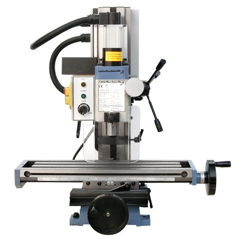
Here are some links to what i am using for controller and the mill.
HiTorque Mini Mill
CNC Spindle Control Upgrade Kit for SX2, SC2
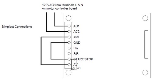
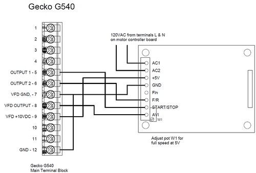
here are some images of the connections:

HiTorque Mini Mill

spindle control pic 1

spindle control pic 2
HiTorque Mini Mill
CNC Spindle Control Upgrade Kit for SX2, SC2
here are some images of the connections:

HiTorque Mini Mill

spindle control pic 1

spindle control pic 2
Please Log in or Create an account to join the conversation.
- PCW
-

- Away
- Moderator
-

Less
More
- Posts: 19129
- Thank you received: 5282
22 Aug 2013 09:22 - 22 Aug 2013 09:22 #37946
by PCW
Replied by PCW on topic 5i25+7i76 Spindle control issue
How is the 7I76 wired to the motor controller board?
it should be:
7I76 TB4 pin 1 SPINDLE- --> Motorcontroller GND
7I76 TB4 pin 2 SPINDLE OUT --> Motorcontroller AVI
7I76 TB4 pin 3 SPINDLE+ --> Motorcontroller +5V
7I76 TB4 pin 5 SPINDLE ENA- --> Motor controller GND
7I76 TB4 pin 6 SPINDLE ENA+ --> Motor controller START/STOP
7I76 TB4 pin 7 SPINDLE DIR- --> Motor controller GND
7I76 TB4 pin 8 SPINDLE DIR+ --> Motor controller F/R
Last edit: 22 Aug 2013 09:22 by PCW.
Please Log in or Create an account to join the conversation.
- johnjsb
- Offline
- New Member
-

Less
More
- Posts: 18
- Thank you received: 0
22 Aug 2013 18:50 #37961
by johnjsb
Replied by johnjsb on topic 5i25+7i76 Spindle control issue
7I76 TB4 pin 1 SPINDLE- --> Motorcontroller GND
7I76 TB4 pin 2 SPINDLE OUT --> Motorcontroller AVI
7I76 TB4 pin 3 SPINDLE+ --> +10Vdc Power Supply
7I76 TB4 pin 5 SPINDLE ENA- --> Floating didn't know it had to be used i thought these were just inverted signal
7I76 TB4 pin 6 SPINDLE ENA+ --> Motor controller START/STOP
7I76 TB4 pin 7 SPINDLE DIR- --> Floating
7I76 TB4 pin 8 SPINDLE DIR+ --> Motor controller F/R
so the 2 i left floating need to be grounded? i was under the impression they were outputs.
Please Log in or Create an account to join the conversation.
- PCW
-

- Away
- Moderator
-

Less
More
- Posts: 19129
- Thank you received: 5282
22 Aug 2013 19:23 #37964
by PCW
Replied by PCW on topic 5i25+7i76 Spindle control issue
The 7I76 spindle enable and direction outputs are floating switches (optocoupler outputs). Each is a independent isolated switch so you always need to use both + and - connections of each.
Please Log in or Create an account to join the conversation.
- andypugh
-

- Offline
- Moderator
-

Less
More
- Posts: 23527
- Thank you received: 5005
22 Aug 2013 20:17 #37969
by andypugh
Replied by andypugh on topic 5i25+7i76 Spindle control issue
It is worth bearing in mind that in the case of many of those mills (with the KBIC motor controller) the speed-adjust pot sits at +100V.
I _think_ that the Mesa 7i76 spindle control is happy with this situation, and that you probably don't need the SC2, but you would want confirmation from PCW on that matter.
I _think_ that the Mesa 7i76 spindle control is happy with this situation, and that you probably don't need the SC2, but you would want confirmation from PCW on that matter.
Please Log in or Create an account to join the conversation.
- johnjsb
- Offline
- New Member
-

Less
More
- Posts: 18
- Thank you received: 0
22 Aug 2013 20:51 #37971
by johnjsb
Replied by johnjsb on topic 5i25+7i76 Spindle control issue
I believe the KBIC controller is for the older model mini mill, never the less good info on that controller. i happen to have one around here that i was going to use for a lathe conversion so thats nice to know. This controller is a brushless controller with a add on board that gives a proper signal.
Please Log in or Create an account to join the conversation.
Moderators: cmorley
Time to create page: 0.075 seconds
