7i77 wiring optical limit switches.
- sliptonic
- Offline
- Premium Member
-

Less
More
- Posts: 140
- Thank you received: 20
05 Mar 2015 05:52 - 05 Mar 2015 05:53 #56482
by sliptonic
7i77 wiring optical limit switches. was created by sliptonic
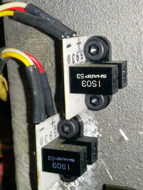
I have opto-interrupters for home/limit switches on a machine I'm reworking. I don't know much about them but they appear to have all the electronics included in a potted blister. There's three wires coming off the board like this
I'm trying to connect them to a 5i25/7i77 combo.
This would be my naive guess.
the positive side of my field power supply to TB2-5
Negative side of power supply to TB2-8
Switch (-) to TB2-8
Switch (+) to TB2-1
The remaining switch conductor (sig?) to TB8-1
My understanding and confidence is limited so any advice is appreciated.
Last edit: 05 Mar 2015 05:53 by sliptonic. Reason: fix image
Please Log in or Create an account to join the conversation.
- emcPT
-

- Offline
- Platinum Member
-

Less
More
- Posts: 702
- Thank you received: 139
05 Mar 2015 06:08 #56486
by emcPT
Replied by emcPT on topic 7i77 wiring optical limit switches.
Hello,
You should know first how those work and what voltage are they meant to work with.
Connecting them to 24V can damage them if they are intended to work with only 5VDC.
My best advice for now is to look for documentation, if not available start with 5VDC between + and - and try to see what happens to the other lead when you pass something on the sensor (if the voltage there changes).
Please Log in or Create an account to join the conversation.
- sliptonic
- Offline
- Premium Member
-
Less
More
- Posts: 140
- Thank you received: 20
05 Mar 2015 06:18 #56487
by sliptonic
Replied by sliptonic on topic 7i77 wiring optical limit switches.
I've searched for documentation for days and found nothing. These were made in the mid 80's so that doesn't surprise me too much.
The + side of the switches are all on a common supply run that also includes a pneumatic solenoid and a magnetic brake. The brake is marked 24V and the datasheet I found for the solenoid says 12/24V.
I wired a 9V battery between the + and - terminals as you suggested. Connecting my multimeter between negative and the third lead shows no change when the gate is blocked.
Connecting the meter between + and the third lead shows 9V when the gate is closed and almost nothing with it open.
Please Log in or Create an account to join the conversation.
- PCW
-

- Away
- Moderator
-

Less
More
- Posts: 19070
- Thank you received: 5261
05 Mar 2015 08:08 - 05 Mar 2015 08:09 #56489
by PCW
Replied by PCW on topic 7i77 wiring optical limit switches.
Looks like those are NPN or sinking type outputs.
To use them with the 7I77 inputs, you would need to put a 2K 1W
resistor from +24 V to each 7I77 input that connects to a interrupter module
To use them with the 7I77 inputs, you would need to put a 2K 1W
resistor from +24 V to each 7I77 input that connects to a interrupter module
Last edit: 05 Mar 2015 08:09 by PCW.
The following user(s) said Thank You: sliptonic
Please Log in or Create an account to join the conversation.
Moderators: cmorley
Time to create page: 0.157 seconds