What Mesa card for that?
- bkt
-
 Topic Author
- Offline
- Platinum Member
-

- Posts: 1110
- Thank you received: 114
regards
giorgio
Please Log in or Create an account to join the conversation.
- massimodamassa
-

- Offline
- Senior Member
-

- Posts: 45
- Thank you received: 9
Please Log in or Create an account to join the conversation.
- Todd Zuercher
-

- Offline
- Platinum Member
-

- Posts: 4690
- Thank you received: 1434
I have a robot system on 5i26 + 7i76 ... 4axes ... now I would add an other axis .. but with analogue drive mode (so i need 1 encoder input and 1 analogue out at least) ... witch type of card I can add for to do these adictional work??
regards
giorgio
Do you mean a 5i25 or 6i25 + 7i76? (I don't think there is a Mesa card called a 5i26.)
Unfortunately the 7i33 will not work with the DB25 FPGA cards. If that is what you have.
If you only need to add one analog axis, and you are not using the encoder counter on the 7i76, you could just add a 7i83 to get some analog output channels. (It would connect to the SmartSerial port on the 7i76.)
If you need more than one encoder, you will need to add a 7i85 or a 7i77. (If you use the 7i77, you wouldn't need the 7i83.)
As far as I know the only options for reading encoders with the DB25 cards, other than a direct single ended connection, are the 7i85(s) and the 7i77.
Please Log in or Create an account to join the conversation.
- bkt
-
 Topic Author
- Offline
- Platinum Member
-

- Posts: 1110
- Thank you received: 114
regards
giorgio
Please Log in or Create an account to join the conversation.
- PCW
-

- Away
- Moderator
-

- Posts: 17515
- Thank you received: 5120
This has 4 DB25 connectors so could support up to 4 7I77s or 24 Axis of encoder/analog out
Another option would be a 7I80HD (3X 50 pin connectors) with one 7I53 (12X encoder input) and one 7I52 (6X encoder input and 6X SSerial) daughtercards then adding 3x 7I83 for the 18 analog outputs
Please Log in or Create an account to join the conversation.
- Todd Zuercher
-

- Offline
- Platinum Member
-

- Posts: 4690
- Thank you received: 1434
If you need to connect 18 servos+encoders, I think I would start with a 6i24 (or 5i24 for PCI, or 7i80HD for Ethernet), plus one 7i53 (12 encoders+2 SSports), plus
Another option using the DB25 style cards would be to use an Ethernet 7i80DB (it has 4 DB25 ports) plus three 7i77 cards.
(What in the world do you need 18 servos for? Sounds like a fun project. Remember Linuxcnc only supports up to 9 axis of motion. (Not sure what the real joint limit is in Master but the user interfaces stop at 9 there as well.)
Please Log in or Create an account to join the conversation.
- bkt
-
 Topic Author
- Offline
- Platinum Member
-

- Posts: 1110
- Thank you received: 114
(What in the world do you need 18 servos for? Sounds like a fun project. Remember Linuxcnc only supports up to 9 axis of motion. (Not sure what the real joint limit is in Master but the user interfaces stop at 9 there as well.)
just ask to mail list ... with some modification code is possible ... without not possible ... fortunately is for 16/18 axis robot so there are 2 option: rtethernet with exchange of data for cordinate 2 different kinematics on two different Lcnc Pc ... or increase Lcnc code with XX, YY, ZZ, aa, BB, CC etc etc ... I think I test solution 1 and 2 too.
If someone have some other ideas ... welcome.
regards
Giorgio
Please Log in or Create an account to join the conversation.
- andypugh
-

- Offline
- Moderator
-

- Posts: 19754
- Thank you received: 4586
So, I think that all is needed, in theory, is to increase EMCMOT_MAX_JOINTS
github.com/LinuxCNC/linuxcnc/blob/master...tion/emcmotcfg.h#L23
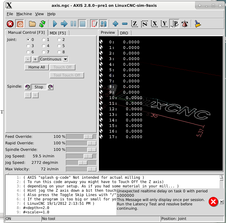
A bit of work is needed to make Axis display a radio button for all the axes, and currently the number of PIDs in HAL is limited to 16 (easy fix).
But other than that, things seem to work.
halcmd: show pin *motor-pos-cmd
Component Pins:
Owner   Type  Dir         Value  Name
    19  float OUT        0.1009  joint.0.motor-pos-cmd ==> J0:pos-cmd
    19  float OUT        0.1009  joint.1.motor-pos-cmd ==> J1:pos-cmd
    19  float OUT             0  joint.10.motor-pos-cmd ==> J10:pos-cmd
    19  float OUT             0  joint.11.motor-pos-cmd ==> J11:pos-cmd
    19  float OUT        0.1009  joint.12.motor-pos-cmd ==> J12:pos-cmd
    19  float OUT        0.1009  joint.13.motor-pos-cmd ==> J13:pos-cmd
    19  float OUT        0.1009  joint.14.motor-pos-cmd ==> J14:pos-cmd
    19  float OUT        0.1009  joint.15.motor-pos-cmd ==> J15:pos-cmd
    19  float OUT        0.1009  joint.16.motor-pos-cmd ==> J16:pos-cmd
    19  float OUT        0.1009  joint.17.motor-pos-cmd ==> J17:pos-cmd
    19  float OUT        0.1009  joint.2.motor-pos-cmd ==> J2:pos-cmd
    19  float OUT        0.1009  joint.3.motor-pos-cmd ==> J3:pos-cmd
    19  float OUT        0.1009  joint.4.motor-pos-cmd ==> J4:pos-cmd
    19  float OUT        0.1009  joint.5.motor-pos-cmd ==> J5:pos-cmd
    19  float OUT             0  joint.6.motor-pos-cmd ==> J6:pos-cmd
    19  float OUT             0  joint.7.motor-pos-cmd ==> J7:pos-cmd
    19  float OUT             0  joint.8.motor-pos-cmd ==> J8:pos-cmd
19 float OUT 0 joint.9.motor-pos-cmd ==> J9:pos-cmdPlease Log in or Create an account to join the conversation.
- bkt
-
 Topic Author
- Offline
- Platinum Member
-

- Posts: 1110
- Thank you received: 114
I not thinks was so big problem modify axis gui. A 19" screen resolution 1280*xxx is big enough for containing all checkbox needed.
Monday I try to improve these modification. If work I will share the result on my github.
regards
giorgio
Please Log in or Create an account to join the conversation.
- Todd Zuercher
-

- Offline
- Platinum Member
-

- Posts: 4690
- Thank you received: 1434
If you would find it helpful I could share the config files with you for it. That example is only has 4 axis router with 2 Z axis. Normally the 2nd Z is defined as W, but to take advantage of the new trajectory planner only XYZ can be used, so I created this config to temporarily slave the W to the Z so that code using only XYZ can be used to run it. I did this all in hal, and it is very sensitive to thread ordering. It would probably work better and be more robust, if it was done with a custom kinematics file, but I don't have the C programming skills to pull that off (at least not yet).
Please Log in or Create an account to join the conversation.

