- Configuring LinuxCNC
- Configuration Tools
- PnCConf Wizard
- Pin does not exist error for limit switch input
Pin does not exist error for limit switch input
- diane
- Offline
- New Member
-

Less
More
- Posts: 6
- Thank you received: 0
27 Mar 2022 04:23 #238440
by diane
Pin does not exist error for limit switch input was created by diane
Hi, I'm building my first CNC machine using a 7i76E and it is working well and moving correctly but I am now trying to implement automatic homing using switches and am having some trouble.
In Pncconf I have Input 0 on TB6 to be Home X and have wired the switch accordingly but every time I try to run the program LinuxCNC terminates with an error saying "Pin 'hm2_7i76e.0.7i76.0.0.input-00' does not exist". The full error is below. If anyone has any ideas about it isn't working I would really appreciate it. Thanks.
Print file information:
RUN_IN_PLACE=no
LINUXCNC_DIR=
LINUXCNC_BIN_DIR=/usr/bin
LINUXCNC_TCL_DIR=/usr/lib/tcltk/linuxcnc
LINUXCNC_SCRIPT_DIR=
LINUXCNC_RTLIB_DIR=/usr/lib/linuxcnc/modules
LINUXCNC_CONFIG_DIR=
LINUXCNC_LANG_DIR=/usr/lib/tcltk/linuxcnc/msgs
INIVAR=inivar
HALCMD=halcmd
LINUXCNC_EMCSH=/usr/bin/wish8.6
LINUXCNC - 2.8.1
Machine configuration directory is '/home/pi/linuxcnc/configs/test_21_3_2'
Machine configuration file is 'test_21_3_2.ini'
INIFILE=/home/pi/linuxcnc/configs/test_21_3_2/test_21_3_2.ini
VERSION=1.1
PARAMETER_FILE=linuxcnc.var
TASK=milltask
HALUI=halui
DISPLAY=axis
COORDINATES=XYZ
KINEMATICS=trivkins coordinates=XYZ
Starting LinuxCNC...
Starting LinuxCNC server program: linuxcncsvr
Loading Real Time OS, RTAPI, and HAL_LIB modules
Starting LinuxCNC IO program: io
Starting HAL User Interface program: halui
Found file(REL): ./test_21_3_2.hal
Shutting down and cleaning up LinuxCNC...
Running HAL shutdown script
hm2: loading Mesa HostMot2 driver version 0.15
hm2_eth: loading Mesa AnyIO HostMot2 ethernet driver version 0.2
hm2_eth: 10.10.10.10: INFO: Hardware address (MAC): 00:60:1b:10:4b:6b
hm2_eth: discovered 7I76E-16
hm2/hm2_7i76e.0: Low Level init 0.15
hm2/hm2_7i76e.0: Smart Serial Firmware Version 43
hm2/hm2_7i76e.0: 51 I/O Pins used:
hm2/hm2_7i76e.0: IO Pin 000 (P1-01): StepGen #0, pin Direction (Output)
hm2/hm2_7i76e.0: IO Pin 001 (P1-14): StepGen #0, pin Step (Output)
hm2/hm2_7i76e.0: IO Pin 002 (P1-02): StepGen #1, pin Direction (Output)
hm2/hm2_7i76e.0: IO Pin 003 (P1-15): StepGen #1, pin Step (Output)
hm2/hm2_7i76e.0: IO Pin 004 (P1-03): StepGen #2, pin Direction (Output)
hm2/hm2_7i76e.0: IO Pin 005 (P1-16): StepGen #2, pin Step (Output)
hm2/hm2_7i76e.0: IO Pin 006 (P1-04): StepGen #3, pin Direction (Output)
hm2/hm2_7i76e.0: IO Pin 007 (P1-17): StepGen #3, pin Step (Output)
hm2/hm2_7i76e.0: IO Pin 008 (P1-05): StepGen #4, pin Direction (Output)
hm2/hm2_7i76e.0: IO Pin 009 (P1-06): StepGen #4, pin Step (Output)
hm2/hm2_7i76e.0: IO Pin 010 (P1-07): IOPort
hm2/hm2_7i76e.0: IO Pin 011 (P1-08): IOPort
hm2/hm2_7i76e.0: IO Pin 012 (P1-09): IOPort
hm2/hm2_7i76e.0: IO Pin 013 (P1-10): IOPort
hm2/hm2_7i76e.0: IO Pin 014 (P1-11): Encoder #0, pin Index (Input)
hm2/hm2_7i76e.0: IO Pin 015 (P1-12): Encoder #0, pin B (Input)
hm2/hm2_7i76e.0: IO Pin 016 (P1-13): Encoder #0, pin A (Input)
hm2/hm2_7i76e.0: IO Pin 017 (P2-01): IOPort
hm2/hm2_7i76e.0: IO Pin 018 (P2-14): IOPort
hm2/hm2_7i76e.0: IO Pin 019 (P2-02): IOPort
hm2/hm2_7i76e.0: IO Pin 020 (P2-15): IOPort
hm2/hm2_7i76e.0: IO Pin 021 (P2-03): IOPort
hm2/hm2_7i76e.0: IO Pin 022 (P2-16): IOPort
hm2/hm2_7i76e.0: IO Pin 023 (P2-04): IOPort
hm2/hm2_7i76e.0: IO Pin 024 (P2-17): IOPort
hm2/hm2_7i76e.0: IO Pin 025 (P2-05): IOPort
hm2/hm2_7i76e.0: IO Pin 026 (P2-06): IOPort
hm2/hm2_7i76e.0: IO Pin 027 (P2-07): IOPort
hm2/hm2_7i76e.0: IO Pin 028 (P2-08): IOPort
hm2/hm2_7i76e.0: IO Pin 029 (P2-09): IOPort
hm2/hm2_7i76e.0: IO Pin 030 (P2-10): IOPort
hm2/hm2_7i76e.0: IO Pin 031 (P2-11): IOPort
hm2/hm2_7i76e.0: IO Pin 032 (P2-12): IOPort
hm2/hm2_7i76e.0: IO Pin 033 (P2-13): IOPort
hm2/hm2_7i76e.0: IO Pin 034 (P3-01): IOPort
hm2/hm2_7i76e.0: IO Pin 035 (P3-14): IOPort
hm2/hm2_7i76e.0: IO Pin 036 (P3-02): IOPort
hm2/hm2_7i76e.0: IO Pin 037 (P3-15): IOPort
hm2/hm2_7i76e.0: IO Pin 038 (P3-03): IOPort
hm2/hm2_7i76e.0: IO Pin 039 (P3-16): IOPort
hm2/hm2_7i76e.0: IO Pin 040 (P3-04): IOPort
hm2/hm2_7i76e.0: IO Pin 041 (P3-17): IOPort
hm2/hm2_7i76e.0: IO Pin 042 (P3-05): IOPort
hm2/hm2_7i76e.0: IO Pin 043 (P3-06): IOPort
hm2/hm2_7i76e.0: IO Pin 044 (P3-07): IOPort
hm2/hm2_7i76e.0: IO Pin 045 (P3-08): IOPort
hm2/hm2_7i76e.0: IO Pin 046 (P3-09): IOPort
hm2/hm2_7i76e.0: IO Pin 047 (P3-10): IOPort
hm2/hm2_7i76e.0: IO Pin 048 (P3-11): IOPort
hm2/hm2_7i76e.0: IO Pin 049 (P3-12): IOPort
hm2/hm2_7i76e.0: IO Pin 050 (P3-13): IOPort
hm2/hm2_7i76e.0: registered
hm2_eth: in hm2_eth_reset
hm2_eth: HostMot2 ethernet driver unloaded
hm2: unloading
Removing HAL_LIB, RTAPI, and Real Time OS modules
Removing NML shared memory segments
Debug file information:
Note: Using POSIX realtime
./test_21_3_2.hal:31: Pin 'hm2_7i76e.0.7i76.0.0.input-00' does not exist
18029
Stopping realtime threads
Unloading hal components
Note: Using POSIX realtime
Attachments:
Please Log in or Create an account to join the conversation.
- Clive S
- Offline
- Platinum Member
-

Less
More
- Posts: 2204
- Thank you received: 486
27 Mar 2022 07:32 #238441
by Clive S
Replied by Clive S on topic Pin does not exist error for limit switch input
Please Log in or Create an account to join the conversation.
- diane
- Offline
- New Member
-
Less
More
- Posts: 6
- Thank you received: 0
27 Mar 2022 08:48 #238442
by diane
Replied by diane on topic Pin does not exist error for limit switch input
Yes TB1 is powered from the 24V power supply
Please Log in or Create an account to join the conversation.
- Clive S
- Offline
- Platinum Member
-
Less
More
- Posts: 2204
- Thank you received: 486
27 Mar 2022 09:14 #238444
by Clive S
Is W1 in the correct position.
from the manual:-
GENERAL
Hardware setup jumper positions assume that the 7I76E card is oriented in an
upright position, that is, with the host interface RJ-45 connector pointing towards the left.
VIN POWER SOURCE
The isolated field I/O on the 7I76E runs from a switching power supply that can be
powered by field power or a separate supply (VIN) with ground common with field power.
Normally the 7I76E will be powered with field power and an on card jumper, W1 allows VIN
to be connected to field power. If you wish to use a single power supply for the 7I76Es field
outputs and field logic power, W1 should be placed in the left hand position. This connects
field power to VIN. If you wish to use a separate supply for VIN, W1 Should be placed in
the right hand position.
LOGIC SECTION POWER
The 7I76E can get its 5V Ethernet, encoder, step/dir and serial interface power from
connector P3 or the on card logic power regulator can be used with unregulated DC power
supplied to TB3. When the on card regulator is used, the maximum power available from
the encoder, serial, and 26 pin expansion connectors is 2A total. If isolation of field power
and logic power is not required, a common 8 to 32VDC power supply can be used for all
7I76E power.
Replied by Clive S on topic Pin does not exist error for limit switch input
Yes TB1 is powered from the 24V power supply
Is W1 in the correct position.
from the manual:-
GENERAL
Hardware setup jumper positions assume that the 7I76E card is oriented in an
upright position, that is, with the host interface RJ-45 connector pointing towards the left.
VIN POWER SOURCE
The isolated field I/O on the 7I76E runs from a switching power supply that can be
powered by field power or a separate supply (VIN) with ground common with field power.
Normally the 7I76E will be powered with field power and an on card jumper, W1 allows VIN
to be connected to field power. If you wish to use a single power supply for the 7I76Es field
outputs and field logic power, W1 should be placed in the left hand position. This connects
field power to VIN. If you wish to use a separate supply for VIN, W1 Should be placed in
the right hand position.
LOGIC SECTION POWER
The 7I76E can get its 5V Ethernet, encoder, step/dir and serial interface power from
connector P3 or the on card logic power regulator can be used with unregulated DC power
supplied to TB3. When the on card regulator is used, the maximum power available from
the encoder, serial, and 26 pin expansion connectors is 2A total. If isolation of field power
and logic power is not required, a common 8 to 32VDC power supply can be used for all
7I76E power.
Please Log in or Create an account to join the conversation.
- diane
- Offline
- New Member
-
Less
More
- Posts: 6
- Thank you received: 0
27 Mar 2022 09:25 - 27 Mar 2022 09:26 #238445
by diane
Replied by diane on topic Pin does not exist error for limit switch input
I have it in the left hand position because I've only got one power source connected as shown in the connection sheet. Does that seem right?
Last edit: 27 Mar 2022 09:26 by diane.
Please Log in or Create an account to join the conversation.
- Clive S
- Offline
- Platinum Member
-
Less
More
- Posts: 2204
- Thank you received: 486
27 Mar 2022 10:04 #238447
by Clive S
Can you comment the line out with a # so that linuxcnc will start without error.
# --- HOME-X ---
######net home-x <= hm2_7i76e.0.7i76.0.0.input-00
(also make sure that the - is correct type as sometimes it can get the wrong ascii code)
then use halshow to see the of pins
Or
in a terminal:
halcmd show pin
Replied by Clive S on topic Pin does not exist error for limit switch input
Yes:I have it in the left hand position because I've only got one power source connected as shown in the connection sheet. Does that seem right?
Can you comment the line out with a # so that linuxcnc will start without error.
# --- HOME-X ---
######net home-x <= hm2_7i76e.0.7i76.0.0.input-00
(also make sure that the - is correct type as sometimes it can get the wrong ascii code)
then use halshow to see the of pins
Or
in a terminal:
halcmd show pin
Please Log in or Create an account to join the conversation.
- diane
- Offline
- New Member
-
Less
More
- Posts: 6
- Thank you received: 0
27 Mar 2022 10:24 #238448
by diane
Replied by diane on topic Pin does not exist error for limit switch input
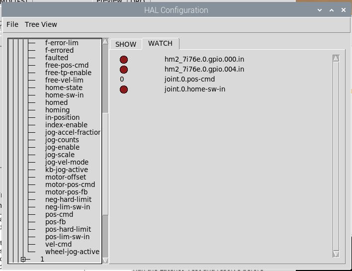
I think one of these is the corresponding pin on Halshow, it doesn't react when I press the switch but on the switch itself there is a built-in LED which does react to the button press.
Attachments:
Please Log in or Create an account to join the conversation.
- Clive S
- Offline
- Platinum Member
-
Less
More
- Posts: 2204
- Thank you received: 486
27 Mar 2022 10:44 - 27 Mar 2022 10:45 #238450
by Clive S
Replied by Clive S on topic Pin does not exist error for limit switch input
in a terminal:
halcmd show pin
the pic is showing different pins to hm2_7i76e.0.7i76.0.0.input-00
so in the hal file try :-
net home-x <= hm2_7i76e.0.gpio.000.in
(I don't have a 7i76e to test)
halcmd show pin
the pic is showing different pins to hm2_7i76e.0.7i76.0.0.input-00
so in the hal file try :-
net home-x <= hm2_7i76e.0.gpio.000.in
(I don't have a 7i76e to test)
Last edit: 27 Mar 2022 10:45 by Clive S.
Please Log in or Create an account to join the conversation.
- PCW
-

- Away
- Moderator
-

Less
More
- Posts: 17980
- Thank you received: 5277
27 Mar 2022 17:57 #238470
by PCW
Replied by PCW on topic Pin does not exist error for limit switch input
hm2_7i76e.0.7i76.0.0.input-XX and hm2_7i76e.0.7i76.0.0.input-XX-not
would be the correct input pins, GPIO pins are not useful here.
The log shows that the field I/O section is not detected:
hm2/hm2_7i76e.0: IO Pin 010 (P1-07): IOPort
hm2/hm2_7i76e.0: IO Pin 011 (P1-08): IOPort
Are the SSerial interface TX and RX lines that connect to the field I/O section
and should look like this:
hm2/hm2_7i76e.0: IO Pin 010 (P1-07): Smart Serial Interface #0, pin tx0 (Output)
hm2/hm2_7i76e.0: IO Pin 011 (P1-08): Smart Serial Interface #0, pin rx0 (Input)
This may be a power wiring or jumper issue or a problem with the 7I76E card.
Is the yellow field power LED (CR8) illuminated?
Please Log in or Create an account to join the conversation.
- diane
- Offline
- New Member
-
Less
More
- Posts: 6
- Thank you received: 0
28 Mar 2022 02:02 #238502
by diane
Replied by diane on topic Pin does not exist error for limit switch input
Yes CR8 is illuminated
Please Log in or Create an account to join the conversation.
Moderators: cmorley
- Configuring LinuxCNC
- Configuration Tools
- PnCConf Wizard
- Pin does not exist error for limit switch input
Time to create page: 0.220 seconds