Axis display tool path / part
- Rick G
-
 Topic Author
- Offline
- Junior Member
-

Less
More
- Posts: 27
- Thank you received: 155
28 Dec 2012 19:33 #28116
by Rick G
Axis display tool path / part was created by Rick G
When milling with AXIS you can display the tool path and if you select a tool the tool representation will change to the proper tool size.
The tool path and the tool path representations also changes when you use cutter radius compensation G41/G42.
linuxcnc.org/docs/devel/html/gcode/tool_...:cutter-compensation
This is great but the resulting part/hole may be different than the display as the display shows the tool path only, not the results.
For example milling a triangle from sheet stock going on the outside path around a triangle and the resulting part (inside) will have sharp corners , but the outside (hole) will have rounded corners.
It seems the option of being able to display the true resulting part/hole and their dimensions would be a great asset.
Rick G
Please Log in or Create an account to join the conversation.
- BigJohnT
-

- Offline
- Administrator
-

Less
More
- Posts: 6999
- Thank you received: 1177
28 Dec 2012 21:27 #28119
by BigJohnT
Replied by BigJohnT on topic Axis display tool path / part
It seems like you could do that if your using cutter comp otherwise the tool path is the center of the tool. The comments I get from commercial shops is they don't even want a back plot... go figure. For me I like to verify that what I programmed resembles what is displayed on the back plot.
John
John
Please Log in or Create an account to join the conversation.
- Rick G
-
 Topic Author
- Offline
- Junior Member
-

Less
More
- Posts: 27
- Thank you received: 155
28 Dec 2012 22:57 #28124
by Rick G
Absolutely, my first cnc set up used a dos program that had no back plot at all. Worked O.K. , but we would load a pen in the spindle and run the program to see what the part would look like.
This was one of the main reasons for looking into EMC2.
Rick G
Replied by Rick G on topic Axis display tool path / part
For me I like to verify that what I programmed resembles what is displayed on the back plot.
Absolutely, my first cnc set up used a dos program that had no back plot at all. Worked O.K. , but we would load a pen in the spindle and run the program to see what the part would look like.
This was one of the main reasons for looking into EMC2.
Rick G
Please Log in or Create an account to join the conversation.
- Rick G
-
 Topic Author
- Offline
- Junior Member
-

Less
More
- Posts: 27
- Thank you received: 155
30 Dec 2012 15:24 #28176
by Rick G
Replied by Rick G on topic Axis display tool path / part
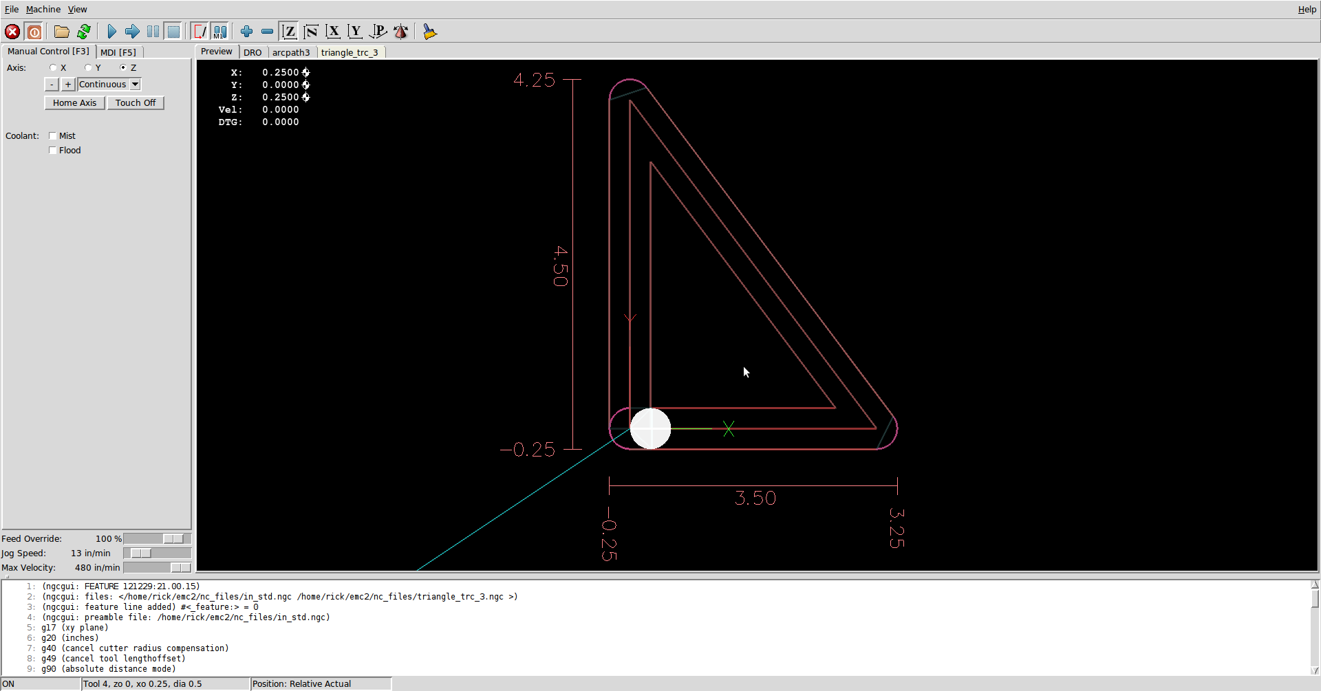
As an example below is a 3" x 4" x 5" triangle.
The center path is with no tool offset and the x and y dimension showed 3.00 and 4.00, the size of the part.
The smallest path is With a 1/4" mill offset to the inside and the dimensions are 2.75, 3.50.
The largest path is with a 1/4" mill offset to the outside and the dimensions are 3.50 and 4.50.
All the dimensions and the paths are correct in that they show where the machine will travel and how far, but they do not show the true shape or dimension of the finished part. When offset to the inside the corners of the triangle would be rounded due to the diameter of the cutter or when offset to the outside the corners would be sharp and the result would be a 3" x 4" x 5" triangle , not a 3.50" x 4.50".
Rick G
Please Log in or Create an account to join the conversation.
Time to create page: 0.264 seconds

