HARDWIRED ESTOP/RESET CIRCUIT
- Benb
-
 Topic Author
- Offline
- Elite Member
-

Less
More
- Posts: 184
- Thank you received: 60
15 Aug 2024 00:40 #307757
by Benb
HARDWIRED ESTOP/RESET CIRCUIT was created by Benb
HARDWIRED ESTOP RESET CIRCUIT
Nomenclature:
CR# – CONTROL RELAY
MCR - MASTER CONTROL RELAY
F# - FUSE
DI – DIGITAL INPUT
DO – DIGITAL OUTPUT
PB – PUSH BUTTON
WDT – WATCH DOG TIMER
L - MAIN SUPPLY LINE 120 VAC – L.F FILTERED LINE
N - MAIN SUPPLY NEUTRAL
PL- Pilot Light
A brief explanation to what this hardwired circuit does follows this diagram.
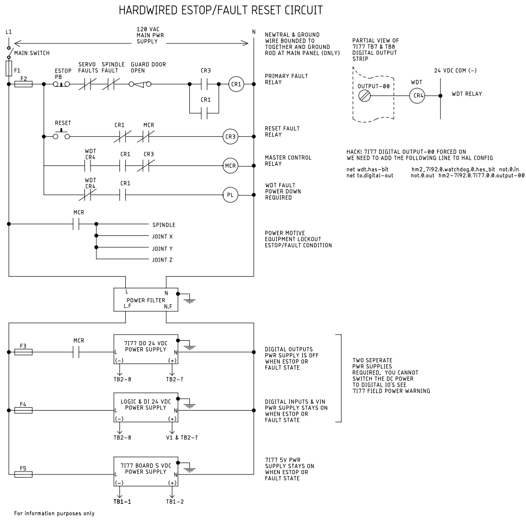
The wiring circuit diagram above is a hardwired circuit that will allow power to be removed from digital outputs, servos and spindle etc. Lockout power in case of WDT active.
The circuit achieves the following:
Nomenclature:
CR# – CONTROL RELAY
MCR - MASTER CONTROL RELAY
F# - FUSE
DI – DIGITAL INPUT
DO – DIGITAL OUTPUT
PB – PUSH BUTTON
WDT – WATCH DOG TIMER
L - MAIN SUPPLY LINE 120 VAC – L.F FILTERED LINE
N - MAIN SUPPLY NEUTRAL
PL- Pilot Light
A brief explanation to what this hardwired circuit does follows this diagram.
The wiring circuit diagram above is a hardwired circuit that will allow power to be removed from digital outputs, servos and spindle etc. Lockout power in case of WDT active.
The circuit achieves the following:
- If power is lost during operation the machine will not restart when power is re-established.
- If an Estop is activated or a fault occurs during operation, the circuit will inhibit (prevent) power to digital outputs, servos and spindle. The rest of the machine control circuit will stay ON; this will enable you to troubleshoot and resume operation without major reinitialization of the machine (maybe).
- Machine will not restart until all faults are cleared and operator presses reset button.
- If watchdog timer HAS bit, NO fault exists and reset button is pressed, the pilot warning light will turn ON, requiring operator to cycle main power off/on to try to reset WDT.
Attachments:
Please Log in or Create an account to join the conversation.
Time to create page: 0.088 seconds