Closing the loop with linear encoders
- Muzzer
- Offline
- Elite Member
-

Less
More
- Posts: 266
- Thank you received: 42
31 Mar 2021 21:07 #204300
by Muzzer
Closing the loop with linear encoders was created by Muzzer
I have my lathe X axis encoder connected up and giving sensible-ish readings when operated open loop ie no encoder feedback.
It's a "5um" scale, ie 200 counts per mm presumably. I have set the INPUT_SCALE to -200, as the encoder counts down when the X direction is positive, assuming the scale value can be signed to indicate polarity.
The servo is set up to move 1mm for every 1000 pulses (STEP_SCALE = 1000). This is for actual moves of the axis ie radius rather than diameter.
If I change the feedback path so that x-pos-fb is now connected to hm2_5i25.0.encoder.02.position, I get a following error ( I have FERROR=10 - should that be increased?). But the hm2_5i25.0.encoder.02.position value is -200 times the value being generated by hm2_5i25.0.stepgen.00.position-fb, so you might think there is a scaling issue still if I simply net them together. How does the encoder scale INPUT_SCALE get applied to the encoder count?
I'm trying to work out if I have a scaling error or a PID issue. One key question I can't fathom is whether these values need to be radius or diameter values. I think the stepgen creates radius distances but can't convince myself that's the case.
Can somebody spot the error here? Many thanks.
# ---closedloop stepper signals---
net x-pos-cmd <= joint.0.motor-pos-cmd
net x-vel-cmd <= joint.0.vel-cmd
net x-output <= hm2_5i25.0.stepgen.00.velocity-cmd
# Default FB from stepgen:
net x-pos-fb <= hm2_5i25.0.stepgen.00.position-fb
# Stepgenposition to PIN x-pos-fb
# Alternative FB from encoder:
# net x-pos-fb <= hm2_5i25.0.encoder.02.position
# Encoderpostion to PIN x-pos-fb
net x-pos-fb => joint.0.motor-pos-fb
INI file:
FERROR = 10
MIN_FERROR = 1.00
MAX_VELOCITY = 50
MAX_ACCELERATION = 100.0
BACKLASH = 0.000
# Encoder counts per machine unit (5um scale?)
INPUT_SCALE = -200
OUTPUT_SCALE = 1.000
# HOME_OFFSET is the offset between home switch and where machine zero
# is to be set. For combined limit and home this should not be negative!!
# I used 2.0 to be clear of the switch
HOME_OFFSET = 2.0
HOME_SEARCH_VEL = 5.0
HOME_LATCH_VEL = 1.0
HOME_USE_INDEX = NO
HOME_IGNORE_LIMITS = YES
HOME_SEQUENCE = 0
# The values below should be 25% larger than MAX_VELOCITY and MAX_ACCELERATION
# If using BACKLASH compensation STEPGEN_MAXACCEL should be 100% larger.
STEPGEN_MAXVEL = 125.00
STEPGEN_MAXACCEL = 7500.00
P = 1000.0
I = 0.0
D = 0.0
FF0 = 0.0
FF1 = 1.0
FF2 = 0.0
BIAS = 0.0
DEADBAND = 0.0
MAX_OUTPUT = 0.0
# these are in nanoseconds
DIRSETUP = 10000
DIRHOLD = 10000
# These were 5000ns. The Lichuan drive supports 600k in diff mode
STEPLEN = 2500
STEPSPACE = 2500
STEP_SCALE = 1000.0
Please Log in or Create an account to join the conversation.
- scotth
- Away
- Elite Member
-
Less
More
- Posts: 242
- Thank you received: 61
01 Apr 2021 02:40 #204350
by scotth
Replied by scotth on topic Closing the loop with linear encoders
Try swapping A and B inputs that should reverse the count direction.
Please Log in or Create an account to join the conversation.
- Hakan
- Offline
- Platinum Member
-

Less
More
- Posts: 1317
- Thank you received: 453
01 Apr 2021 06:16 - 01 Apr 2021 06:20 #204361
by Hakan
Replied by Hakan on topic Closing the loop with linear encoders
It seems to be the scaling.
joint.0.motor-pos-cmd, hm2_5i25.0.stepgen.00.position-fb and hm2_5i25.0.encoder.02.position should be the same or the diff should be small. Move 1mm and all should change by 1.0.
Check your hal file, there should be a linethat's where the scaling is set. Add the line if it isn't there. Adjust the indexes 0 and 2 if I got that wrong.
joint.0.motor-pos-cmd, hm2_5i25.0.stepgen.00.position-fb and hm2_5i25.0.encoder.02.position should be the same or the diff should be small. Move 1mm and all should change by 1.0.
Check your hal file, there should be a line
setp hm2_5i25.0.encoder.02.scale [JOINT_0]INPUT_SCALE
Last edit: 01 Apr 2021 06:20 by Hakan.
Please Log in or Create an account to join the conversation.
- Muzzer
- Offline
- Elite Member
-
Less
More
- Posts: 266
- Thank you received: 42
01 Apr 2021 07:21 - 01 Apr 2021 19:26 #204365
by Muzzer
Replied by Muzzer on topic Closing the loop with linear encoders
Thanks, Hakan - that sounds like the right kind of solution.
Certainly in halshow, the 2 signals change together when I move the axis, apart from the -200 scale factor, so I must be getting close.
I will give that a go!
EDIT - that did the trick. I copied that line into my HAL file and it picked up the -200 scale factor. The reported stegen and encoder positions were then almost identical in Halshow. Replacing hm2_5i25.0.stepgen.00.position-fb by hm2_5i25.0.encoder.02.position closed the loop finally.
Obviously, the original PID values (P=1000) didn't sit well(!!) but I've dialled P back to 1.0 with I and D at zero and it works pretty convincingly. I'm guessing that those values should result in broadly similar behaviour, as the units are the same (mm) and I am still using positional control with the same PID loop(s). I have still to properly tune the LiChuan servo drives and the LinuxCNC PID but for now, I seem to have a working system.
It just needed a bit of gentle Viking power!!
(EDIT - corrected typo)
Last edit: 01 Apr 2021 19:26 by Muzzer.
Please Log in or Create an account to join the conversation.
- andypugh
-

- Offline
- Moderator
-

Less
More
- Posts: 19886
- Thank you received: 4645
02 Apr 2021 22:50 #204568
by andypugh
Replied by andypugh on topic Closing the loop with linear encoders
I would expect a bit of I gain to work well for "tweaking" the motor to match the scale. P-gain can only ever get you close (as with zero error there is no output). A bit of I pulls in that last bit of error.
Please Log in or Create an account to join the conversation.
- Muzzer
- Offline
- Elite Member
-
Less
More
- Posts: 266
- Thank you received: 42
03 Apr 2021 10:18 - 03 Apr 2021 15:22 #204605
by Muzzer
Replied by Muzzer on topic Closing the loop with linear encoders
Hi Andy - I spent a couple of hours yesterday playing with both the X and Z axis tuning, using the config tool and Halscope. The MPG seems to be a convenient means of providing step inputs to the axes.
I started off with the X axis which is a simpler assembly, turning up P from 1 until it started to oscillate around 50, then backed it off to 30 and dialled in some D, trying to speed up the response without significant overshoot. I couldn't improve much on D=5. Finally, some I term. I couldn't see much improvement beyond I=0.2.
With the Z axis, I ended up with P=80, I=0.5 and D=20.
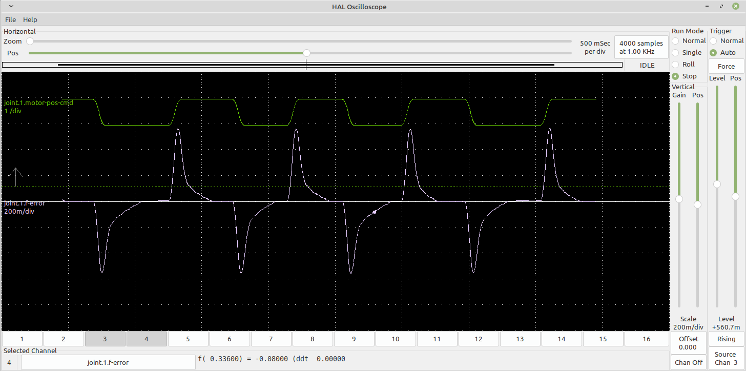
The response is hardly a textbook example of a well tuned servo system. I get a fairly rapid initial move, followed typically by a slower creep up to the final position. Given that P and D are about as high as they can go sensibly, I'm not seeing any great opportunity to improve on that. Ideally I'd be getting there mostly due to the P and D terms, with the I providing a last, steady state adjustment.
There's a lot going on in reality, so this isn't quite a simple mass spring damper type situation. There are 3 factors making life less than straightforward:
So I have 2 hysteretic elements (backlash and encoder resolution) and servo drives with questionable responses. I can feel a battle with the Lichuan servos coming on, otherwise I suspect I am close to what I can expect as a final result.
Given the 5um resolution of the encoders, what is the recommended deadband? I'm guessing somewhere between 2.5 and 5um but I can't figure out a convincing logical answer to that. Certainly, increasing the deadband towards the 5um (0.005) level seems to get rid of much of the grumbling / jittering that arises after some moves.
I seem to have inherited FF1=1, presumably from the original CNCconf setup. The other FF terms are zero. I did play with a couple of them and it didn't end well, with the joint drifting out of position, so I left them as they were. I don't have any high frequency bursts going on but until I reread the docs, I'm not clear if I'm missing anything here.
Finally, how do the STEPGEN_MAXACCEL and STEPGEN_MAXVEL affect the PID behaviour? Presumably they will affect the slope of the rising edge of the demand step I'm using to observe the system response, which would in turn affect the effect of the D feedforward term for instance.
Here's what I have for the Z axis:
Incidentally, what should I specify for the following error? I have 300 at the moment but I'm not even sure of the units....
EDIT - finally got into the Lichuan "software". On my 4th Windows 10 machine, I finally got an installation that actually worked - and spoke English. Then installed the driver for the USB-RS485 serial device and uploaded the parameters from one of the servo drivers. The anticlimax moment came when I saw that the only parameter I can set is the direct P term, which is set to 20. I suppose that simplifies life but I'd hoped for a bit more opportunity for improvement.
I started off with the X axis which is a simpler assembly, turning up P from 1 until it started to oscillate around 50, then backed it off to 30 and dialled in some D, trying to speed up the response without significant overshoot. I couldn't improve much on D=5. Finally, some I term. I couldn't see much improvement beyond I=0.2.
With the Z axis, I ended up with P=80, I=0.5 and D=20.
The response is hardly a textbook example of a well tuned servo system. I get a fairly rapid initial move, followed typically by a slower creep up to the final position. Given that P and D are about as high as they can go sensibly, I'm not seeing any great opportunity to improve on that. Ideally I'd be getting there mostly due to the P and D terms, with the I providing a last, steady state adjustment.
There's a lot going on in reality, so this isn't quite a simple mass spring damper type situation. There are 3 factors making life less than straightforward:
- The mechanisms both have a degree of backlash and although I've taken care to minimise them, they are of the same order as the movements I am trying to optimise ie ~+/-10-20um. I have reasonably good quality Korean ground ballscrews but the lathe itself (Colchester Bantam) has seen better days and the saddle is being driven some way from its centre of mass and the likely line of action of the cutting forces. The Z axis is less ideal than the X, not surprisingly, due to the vee and flat ways and larger mass.
- The encoders have "5um" resolution, so realistically I can't expect to control position much better than somewhere in the region of +/- 5-10um surely.
- The Lichuan servo drives will be a pig to try to tune. The absolute first thing to do in a dual control loop system like this would surely be to get the servos as optimised as possible before playing with the external (LinuxCNC) loop. However, the tuning "software" is no more than a means of downloading and uploading the table of parameters from a PC to the drives and I don't seem to be alone in being unable to even load the "software" on a W10 machine. So I've started out with the standard tune, which I suspect is pretty ropey and must be limiting what I can do.
So I have 2 hysteretic elements (backlash and encoder resolution) and servo drives with questionable responses. I can feel a battle with the Lichuan servos coming on, otherwise I suspect I am close to what I can expect as a final result.
Given the 5um resolution of the encoders, what is the recommended deadband? I'm guessing somewhere between 2.5 and 5um but I can't figure out a convincing logical answer to that. Certainly, increasing the deadband towards the 5um (0.005) level seems to get rid of much of the grumbling / jittering that arises after some moves.
I seem to have inherited FF1=1, presumably from the original CNCconf setup. The other FF terms are zero. I did play with a couple of them and it didn't end well, with the joint drifting out of position, so I left them as they were. I don't have any high frequency bursts going on but until I reread the docs, I'm not clear if I'm missing anything here.
Finally, how do the STEPGEN_MAXACCEL and STEPGEN_MAXVEL affect the PID behaviour? Presumably they will affect the slope of the rising edge of the demand step I'm using to observe the system response, which would in turn affect the effect of the D feedforward term for instance.
Here's what I have for the Z axis:
Incidentally, what should I specify for the following error? I have 300 at the moment but I'm not even sure of the units....
EDIT - finally got into the Lichuan "software". On my 4th Windows 10 machine, I finally got an installation that actually worked - and spoke English. Then installed the driver for the USB-RS485 serial device and uploaded the parameters from one of the servo drivers. The anticlimax moment came when I saw that the only parameter I can set is the direct P term, which is set to 20. I suppose that simplifies life but I'd hoped for a bit more opportunity for improvement.
Attachments:
Last edit: 03 Apr 2021 15:22 by Muzzer.
Please Log in or Create an account to join the conversation.
- andypugh
-
- Offline
- Moderator
-
Less
More
- Posts: 19886
- Thank you received: 4645
03 Apr 2021 16:03 #204633
by andypugh
If the PIF asks for a velocity that is > the MAX then it won't happen. So the PID will be asking for something that doesn't happen.
This should only happen when the PID is saturated, and in a well-behaved system that probably shouldn't happen.
You might want to cap the PID output to match the stepgen limit.
As you noted, the STEPGEN_MAXVEL will cap the D-term input.
Accel is more interesting, as it will delay the effect of the PID, causing a phase shift, which might be enough to cause resonance. But I don't think that there is a way ti internally cap the rate of change of PID output.
Replied by andypugh on topic Closing the loop with linear encoders
Finally, how do the STEPGEN_MAXACCEL and STEPGEN_MAXVEL affect the PID behaviour? Presumably they will affect the slope of the rising edge of the demand step I'm using to observe the system response, which would in turn affect the effect of the D feedforward term for instance.
If the PIF asks for a velocity that is > the MAX then it won't happen. So the PID will be asking for something that doesn't happen.
This should only happen when the PID is saturated, and in a well-behaved system that probably shouldn't happen.
You might want to cap the PID output to match the stepgen limit.
As you noted, the STEPGEN_MAXVEL will cap the D-term input.
Accel is more interesting, as it will delay the effect of the PID, causing a phase shift, which might be enough to cause resonance. But I don't think that there is a way ti internally cap the rate of change of PID output.
Please Log in or Create an account to join the conversation.
- Muzzer
- Offline
- Elite Member
-
Less
More
- Posts: 266
- Thank you received: 42
03 Apr 2021 16:18 - 03 Apr 2021 16:20 #204635
by Muzzer
Replied by Muzzer on topic Closing the loop with linear encoders
Thanks, that makes sense.
BTW - how do I arrive at a sensible value for the following error? Although I have it I set FERROR to 300(??!!) on the Z axis in my INI file, I can cause a follow error if I jog enthusiastically. It doesn't look as if it's actually being used anywhere in the HAL file. Should it be ending up in pid.z.maxerror? That seems to be hard wired at 12.7um if I understand it (and the units) correctly.
Presumably it should be
setp pid.z.maxerror [JOINT_1]FERROR?
#*******************
# AXIS Z JOINT 1
#*******************
setp pid.z.Pgain [JOINT_1]P
setp pid.z.Igain [JOINT_1]I
setp pid.z.Dgain [JOINT_1]D
setp pid.z.bias [JOINT_1]BIAS
setp pid.z.FF0 [JOINT_1]FF0
setp pid.z.FF1 [JOINT_1]FF1
setp pid.z.FF2 [JOINT_1]FF2
setp pid.z.deadband [JOINT_1]DEADBAND
setp pid.z.maxoutput [JOINT_1]MAX_OUTPUT
setp pid.z.error-previous-target true
# This setting is to limit bogus stepgen
# velocity corrections caused by position
# feedback sample time jitter.
setp pid.z.maxerror 0.012700
net z-index-enable <=> pid.z.index-enable
net z-enable => pid.z.enable
net z-pos-cmd => pid.z.command
net z-pos-fb => pid.z.feedback
net z-output <= pid.z.output
# Step Gen signals/setup
setp hm2_5i25.0.stepgen.01.dirsetup [JOINT_1]DIRSETUP
setp hm2_5i25.0.stepgen.01.dirhold [JOINT_1]DIRHOLD
setp hm2_5i25.0.stepgen.01.steplen [JOINT_1]STEPLEN
setp hm2_5i25.0.stepgen.01.stepspace [JOINT_1]STEPSPACE
setp hm2_5i25.0.stepgen.01.position-scale [JOINT_1]STEP_SCALE
setp hm2_5i25.0.stepgen.01.step_type 0
setp hm2_5i25.0.stepgen.01.control-type 1
setp hm2_5i25.0.stepgen.01.maxaccel [JOINT_1]STEPGEN_MAXACCEL
setp hm2_5i25.0.stepgen.01.maxvel [JOINT_1]STEPGEN_MAXVEL
Last edit: 03 Apr 2021 16:20 by Muzzer.
Please Log in or Create an account to join the conversation.
- andypugh
-
- Offline
- Moderator
-
Less
More
- Posts: 19886
- Thank you received: 4645
03 Apr 2021 16:32 #204637
by andypugh
There are two FERROR values. MIN_FERROR for low-speed error and FERROR for high speed.
linuxcnc.org/docs/2.8/html/config/ini-co...t__lt_num_gt_section
It should be small. It is the point at which the system is saying "I am no longer making the part you asked for"
Neither normally appear in HAL (though there is no problem with referencing the values for your own purposes). The motion module reads the values directly from the INI, in the same way as it reads the axis limits on position, velocity etc.
Replied by andypugh on topic Closing the loop with linear encoders
BTW - how do I arrive at a sensible value for the following error? Although I have it I set FERROR to 300(??!!) on the Z axis in my INI file, I can cause a follow error if I jog enthusiastically. It doesn't look as if it's actually being used anywhere in the HAL file.
There are two FERROR values. MIN_FERROR for low-speed error and FERROR for high speed.
linuxcnc.org/docs/2.8/html/config/ini-co...t__lt_num_gt_section
It should be small. It is the point at which the system is saying "I am no longer making the part you asked for"
Neither normally appear in HAL (though there is no problem with referencing the values for your own purposes). The motion module reads the values directly from the INI, in the same way as it reads the axis limits on position, velocity etc.
The following user(s) said Thank You: Muzzer
Please Log in or Create an account to join the conversation.
- Muzzer
- Offline
- Elite Member
-
Less
More
- Posts: 266
- Thank you received: 42
03 Apr 2021 16:46 #204639
by Muzzer
Replied by Muzzer on topic Closing the loop with linear encoders
Thanks. I will leave the setp pid.z.maxerror 0.012700 alone and set the FERROR to something like 0.5 for the moment. Certainly that would seem more appropriate than 300.
Please Log in or Create an account to join the conversation.
Time to create page: 0.125 seconds