Noobie Friendly Wiring Schematic Program
- my1987toyota
-
 Topic Author
- Offline
- Platinum Member
-

- Posts: 994
- Thank you received: 444
to help generate wiring diagrams for my builds . Doing it the old fashion way takes forever especially when showing
a multi color twisted pair of wires. Are their any good open sources programs out their?
Please Log in or Create an account to join the conversation.
- ALittleOffTheRails
-

- Visitor
-

Continue reading only if you want an insight to my madness
I do mostly everything in my head, but I guess I'm just lucky that I can visualize this kind of stuff in my head. Yes I fully understand this is absolutely completely insane and without any sense or reason.
This includes 4 different MESA cards, 7 power supplies controlled by a relay & contactor each. 2 switches per relay. MPG, servo driver for the spindle and all the filtering for the servo driver. I admit I designed some PCBs to help simplify the wiring for the "self holding relays" that control the contactors. The reason for the relay --> contactor arrangement as the contactor coil current was below the wetting current for contacts.
I approach it as a modular approach that just repeats itself.
If I do have to do a wiring diagram it's usually just scribble on the back of the nearest bit of paper with whatever crayon I have near.
Please Log in or Create an account to join the conversation.
- arvidb
-

- Offline
- Platinum Member
-
- Posts: 459
- Thank you received: 158
Please Log in or Create an account to join the conversation.
- my1987toyota
-
Topic Author
- Offline
- Platinum Member
-
- Posts: 994
- Thank you received: 444
Thanks arvidb.I gave a tip about QElectroTech here, maybe that's something you can use?
I will look that one over that may just work.
I also have seen WireViz but the install is a bit tricky.
Please Log in or Create an account to join the conversation.
- my1987toyota
-
Topic Author
- Offline
- Platinum Member
-
- Posts: 994
- Thank you received: 444
Thank you ALittleOffTheRails.ALittleOffTheRails post=233510 userid=31054You might be able to bend Kicad to your will. You would probably have to create symbols for your hardware, eg stepper drivers and such.
Continue reading only if you want an insight to my madness
I do mostly everything in my head, but I guess I'm just lucky that I can visualize this kind of stuff in my head. Yes I fully understand this is absolutely completely insane and without any sense or reason.
This includes 4 different MESA cards, 7 power supplies controlled by a relay & contactor each. 2 switches per relay. MPG, servo driver for the spindle and all the filtering for the servo driver. I admit I designed some PCBs to help simplify the wiring for the "self holding relays" that control the contactors. The reason for the relay --> contactor arrangement as the contactor coil current was below the wetting current for contacts.
I approach it as a modular approach that just repeats itself.
If I do have to do a wiring diagram it's usually just scribble on the back of the nearest bit of paper with whatever crayon I have near.
I have heard of using KiCad that way but haven't tried it myself. I did read your full post by the way.
I wish I could keep that much in my head for years on end. Unfortunately I have to do this in a way
that someone else can possibly trouble shoot any problems in the future. I also have to build this in a way that can
be easily duplicated . I know I will be building more of these machines and I will be using what I have done today
as a foundation for the next builds. Not for resale mind you but so I can expand capabilities in the future.
I already have wire cut lists, expected component placement measurements, ect.
Please Log in or Create an account to join the conversation.
- rodw
-

- Offline
- Platinum Member
-
- Posts: 11994
- Thank you received: 4084
Attachments:
Please Log in or Create an account to join the conversation.
- pippin88
- Offline
- Elite Member
-

- Posts: 263
- Thank you received: 51
It is VERY worthwhile documenting whilst building.
You might remember well during the build, but suddenly it's five years later and trying to double shoot is a nightmare. That scrap of paper you threw out or photo somewhere on an old phone in a draw is not much help.
I haven't looked in a couple of years. Last time I looked I couldn't find a really easy way to do quick wiring diagrams.
I don't need / care about proper symbols. Just want text labels and ability to snap wires to a connector block and colour them and route them vaguely
Please Log in or Create an account to join the conversation.
- spumco
- Offline
- Platinum Member
-
- Posts: 2126
- Thank you received: 882
I don't need / care about proper symbols. Just want text labels and ability to snap wires to a connector block and colour them and route them vaguely
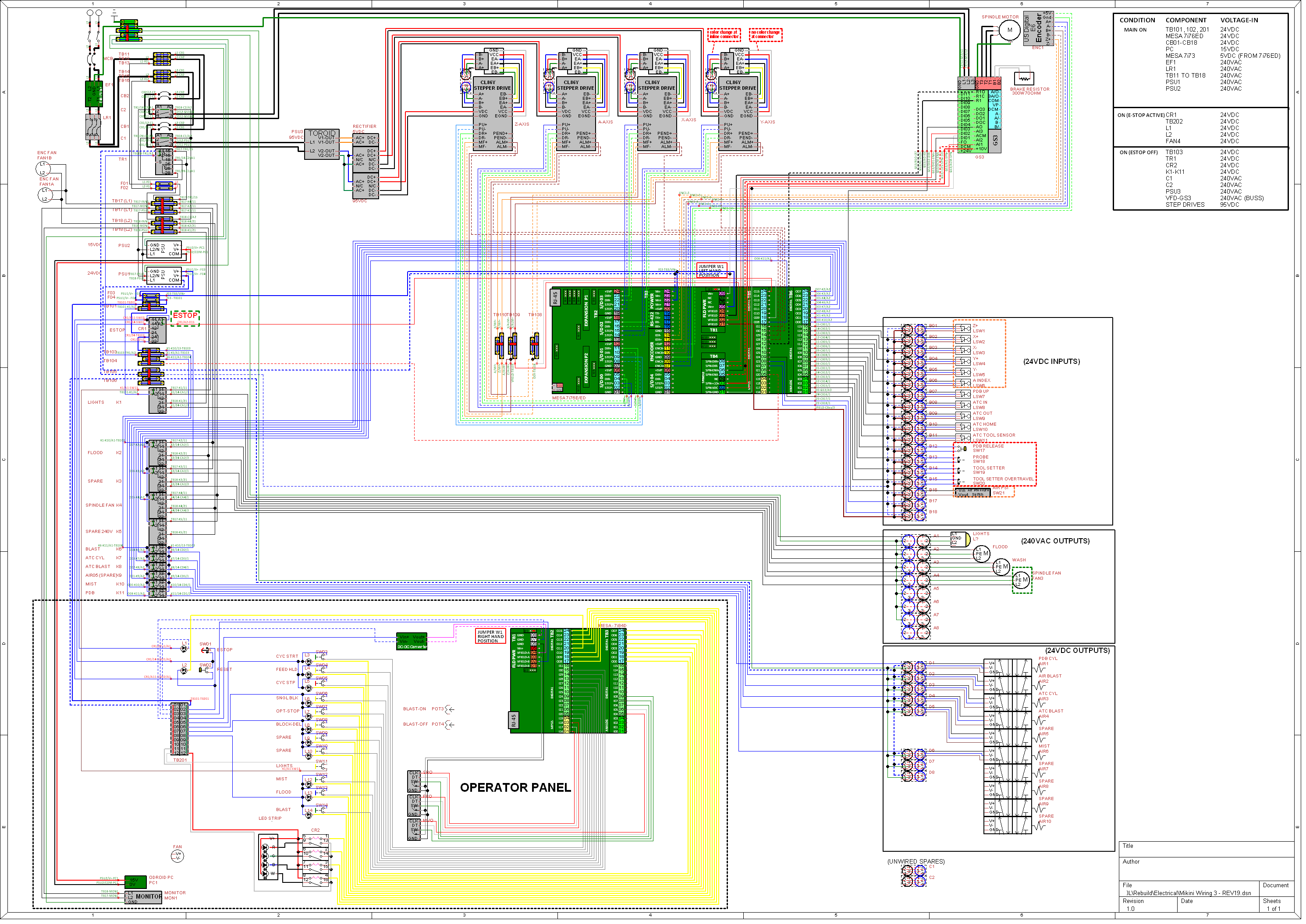
QElectroTech looks like a really nice 'proper' diagram program and I've been fiddling with it since @arvidb mentioned it a couple weeks ago. But for something to do what I think of as a schematic - i.e. how to wire the system up - TinyCAD has been my go-to for a number of years.
Wires snap to pins on any symbol you want, color-coded, line thickness to indicate wire gauge, etc. It's not 'smart' like QElectroTech to span pages, but you can make the drawing as large as you want. Multiple pages are also possible.
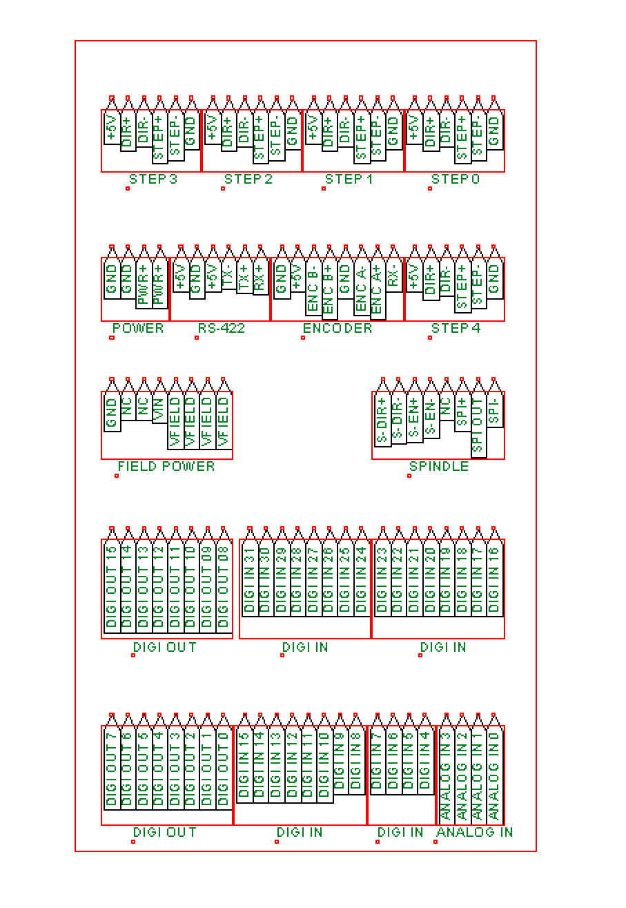
I've even got a number of symbols cooked up for Mesa cards in my home-built symbol library.
I put an example in the other thread @ardvidb linked, but here's another one of my current mill project with a 7i76ED and a 7i84D:
Attachments:
Please Log in or Create an account to join the conversation.
- my1987toyota
-
Topic Author
- Offline
- Platinum Member
-
- Posts: 994
- Thank you received: 444
That has happened to me more times then I care to admit. LOL
You might remember well during the build, but suddenly it's five years later and trying to double shoot is a nightmare. That scrap of paper you threw out or photo somewhere on an old phone in a draw is not much help.
Please Log in or Create an account to join the conversation.
- Beef
-

- Offline
- Senior Member
-

- Posts: 43
- Thank you received: 54
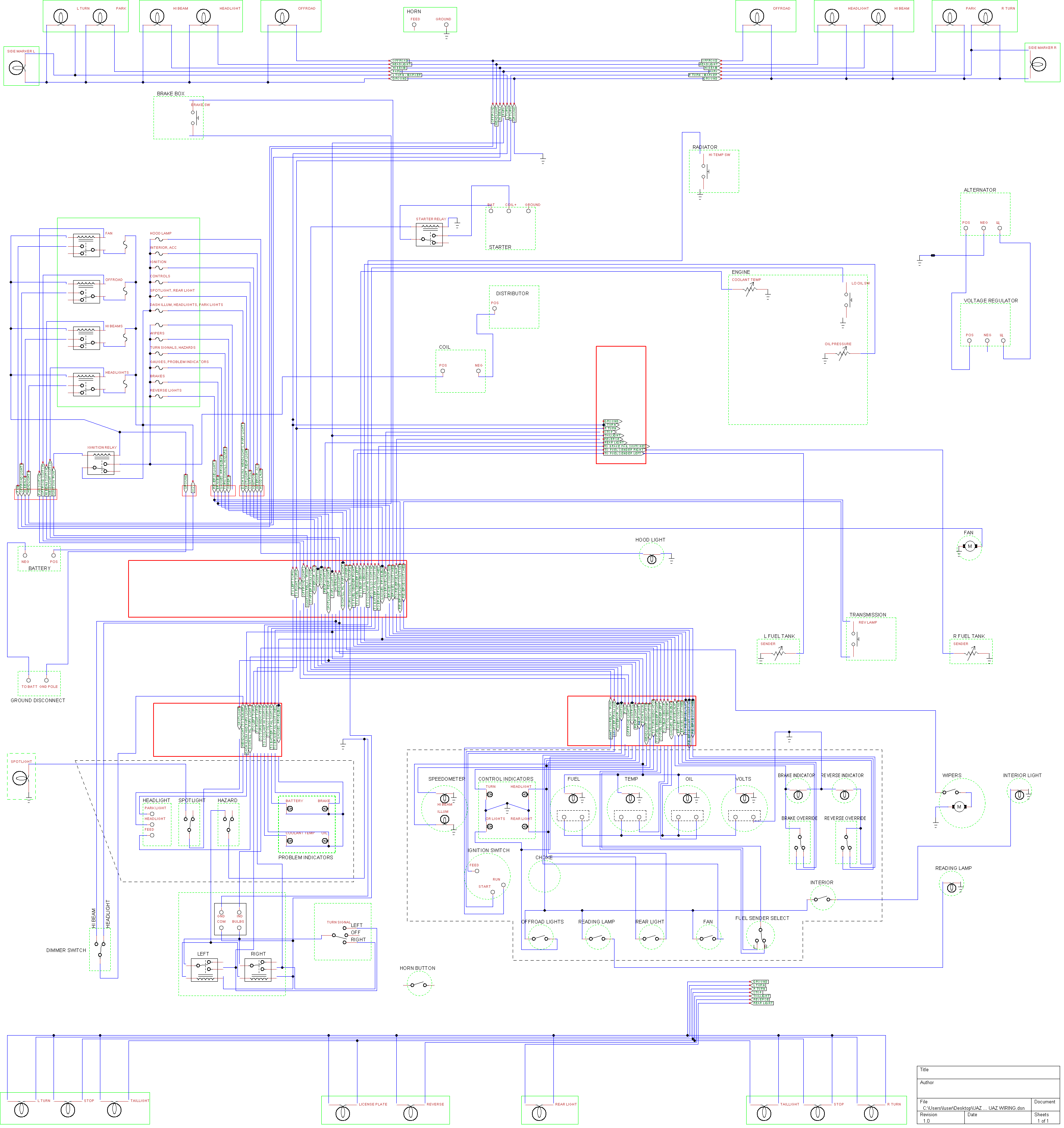
Either way, TinyCAD has been my go-to for wiring schematics, since it's very easy to get started in and has a fair number of QOL features such as auto-incrementing, keeping the label box open as you add multiple of a component, etc. Here's a draft of some car wiring I did for an old UAZ - although I reduced the wiring redundancy a little bit in the final version I don't have an image handy. I was able to print it on several sheets of A4 and tape them together, allowing me to handily reference the diagram when restoring it.
Attachments:
Please Log in or Create an account to join the conversation.