Search Results (Searched for: THCAD)
10 May 2024 17:07 - 10 May 2024 17:13
Replied by shasse on topic Build documentation for our 500W Raycus fiber laser using LinuxCNC and QtPlasmaC
Build documentation for our 500W Raycus fiber laser using LinuxCNC and QtPlasmaC
Category: Plasma & Laser
Here's the full text of the article for posterity and in case something happens with GitHub. I apologize for the formatting, I was fighting with the forum editor for a while and had to remove some links to get the post to submit:
Building a control system for a 500W Raycus fiber laser using LinuxCNC and QtPlasmaC
Introduction
This document describes a project at Madison, WI USA-based hackerspace Sector67 to create a control system for a Raycus 500 Watt fiber laser cutter using LinuxCNC and QtPlasmaC. This project was basically a proof of concept to work out what would be needed to operationalize a LinuxCNC-controlled fiber laser system. The laser source and head were donated to the space and came to us in an unproven state. There were several challenges that needed to be overcome, but in the end we were able to build a solidly functional fiber laser cutting system.
Many thanks to the Sector67 members that contributed to this project, of course Chris Meyer but also Dave Franchino, Ken Delpapa and many others.
Also many thanks to the dedicated volunteers on the LinuxCNC forums who give of their time freely to foster not only an amazing open source project but also a fantastic open source community. In particular for this project Phillip Carter (phillc54), Tom Berisha (tommylight), Peter Wallace (PCW) and Rod Webster (rodw) were very helpful but there are many others. This project stands on the shoulders of those giants. A lot of this article is summarizing and re-hashing conversations that happened on the LinuxCNC forums.
It is important to mention that fiber lasers will absolutely make you blind in an instant. You must be extremely careful when experimenting with or operating a fiber laser. We surrounded ours with an enclosure and added two cameras to enable operator feedback without needing to put human eyes at risk. The information here is provided to capture our process. If you implement a fiber laser you are proceeding at your own risk and should educate yourself about the real risks of these devices.

The laser cutter
The hardware
The laser source
The laser source for this project was a 500 Watt Raycus C500 “Continuous Wave Fiber Laser”. This laser source has various methods of controlling laser power. For this project we are running it in “AD” mode supplying a 0-10V analog voltage for the laser power, a 24VDC for laser modulation, and 24VDC for laser enable. There is an RS232 serial connection on the device, but we were never able to get more than very rudimentary information from the serial connection.
One important note is that if the LinuxCNC control system is sending a “laser enable” +24VDC signal when the laser source is powered up the laser source will enter a fault mode. In our configuration this signal is enabled when the “machine on” state is entered. We are currently resolving this by powering the laser source first and then enabling the machine. In QtPlasmaC this is the “POWER” button. The laser does send a +24VDC “laser ready” signal on the DB25 connector, and we could in theory use this to prevent entering the “machine on” state unless the laser is powered. However, we currently do a lot of machine testing without the laser on at all, so for now we are just manually working around this with awareness and the specific power on procedure.
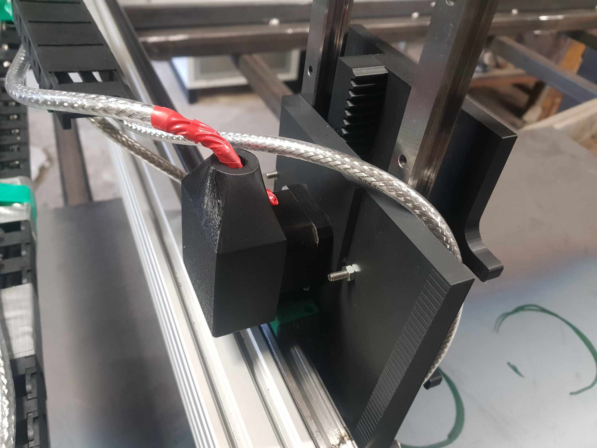
The laser head
Our laser head is a “WSX-MN15” model. This manual focus laser head came to us with what should have been a standalone close-loop capacitive height sensor and control board. We could never get that to work properly, which was not a significant problem because from the beginning we wanted to get closed-loop height control controlled by LinuxCNC. So we ended up gutting the on-head capacitive sense and Z height controls and routing the new sensor (described below), home and float sensors, and Z stepper control back to the main control box.
One note is that in addition to everything we stripped off the head, we adapted the air assist to take a ¼” “push to connect” fitting. The threads on the head were G1/8 (BSPP) straight threads, not NPT. It is important to get that right or you may damage the threads on the head and not have an air tight fitting.
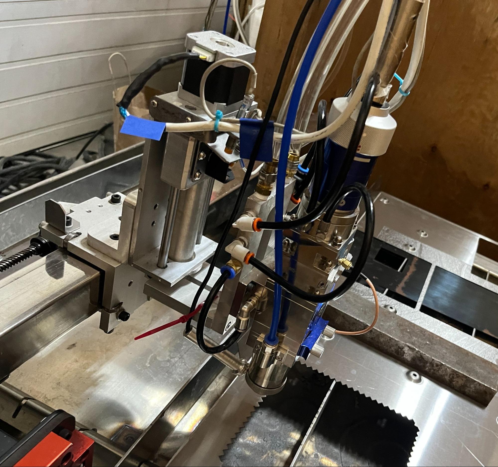
The laser head
The capacitive sensor
We used a BCL-AMP capacitive sensor for laser head height sensing. These capacitive sensors are typically used for height sensing in fiber laser cutting systems. The sensors come potted in an aluminum case with a small coax connector to connect to the laser head and a GX16 4-pin circular aviation connector to drive the device. These sensors look like this:
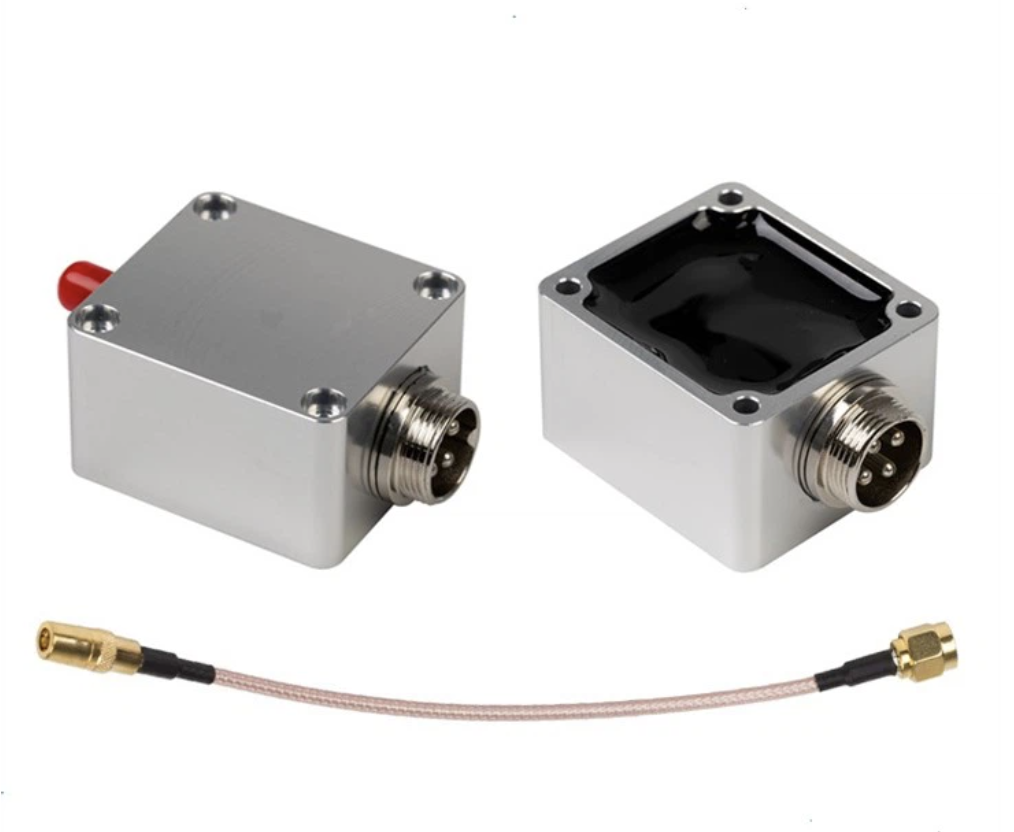
The capacitive amp
There are a number of capacitive sensors with this same basic form factor. We used a “BCL-AMP Amplifier Preamplifier Sensor For Friendess BCS100 Height Controller FSCUT1000 FSCUT2000 System” amp. As of the time this article was written, this amps is available for $52.50 US at www.aliexpress.us/item/3256804585924423.html.
Interfacing the amp to LinuxCNC is described in sections below.
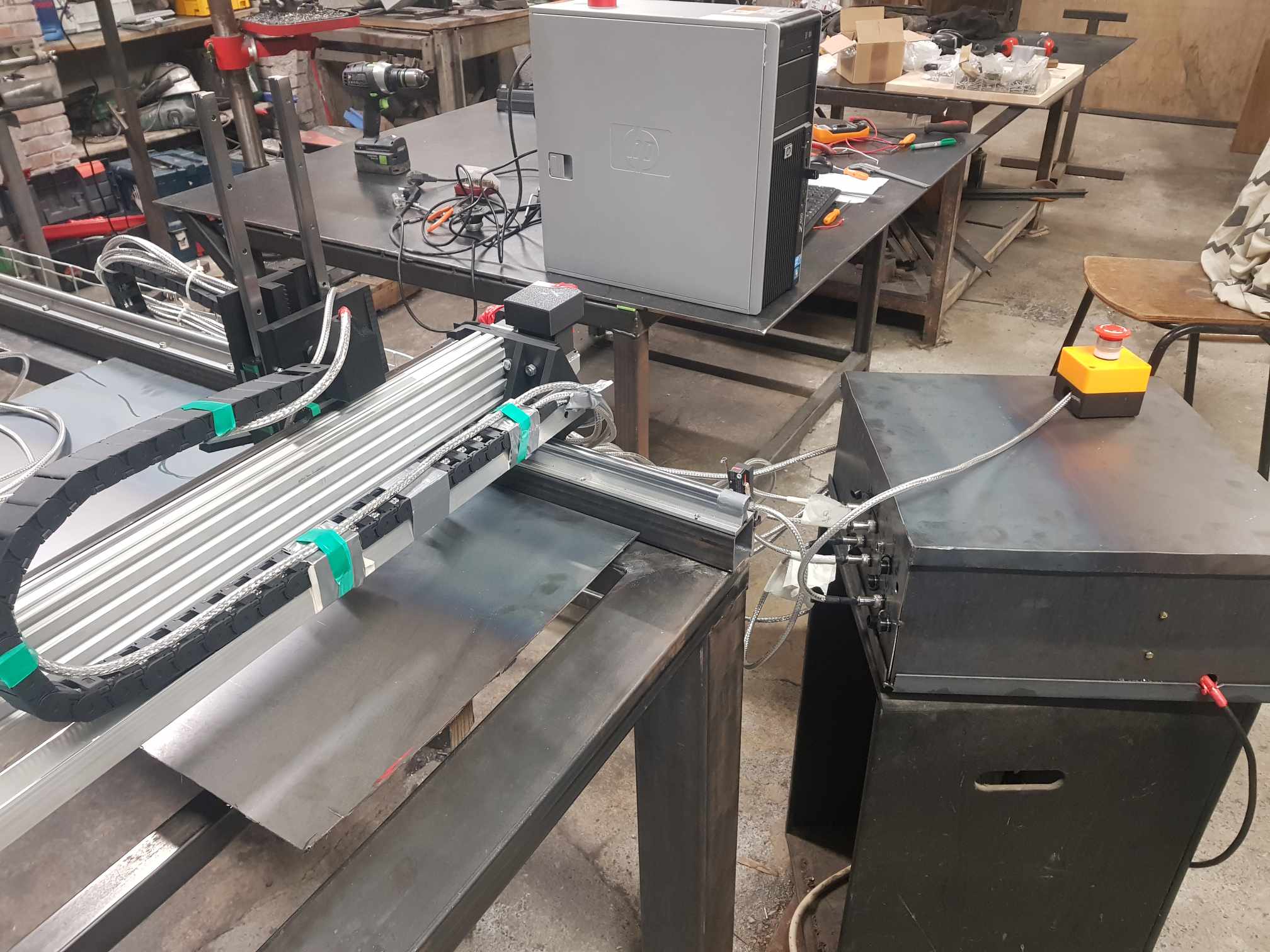
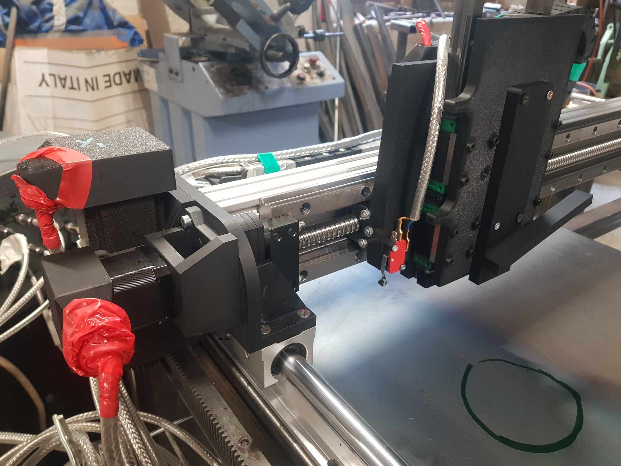
The XY table
The table itself is not really notable. As a prototype platform it has a working area of about 2’x2’ with stepper motor control. It’s not especially fast or rigid unfortunately. There are plenty of other resources for how to get that working with LinuxCNC, so I won’t cover it in too much depth here.
Gas assist
We used a simple 24VDC gas solenoid to control the gas flow. We also implemented a low pressure bypass so that when gas is on there is always some amount of air flowing out of the laser head. This should hopefully prevent any contaminants from getting to the lens when the machine is running.
The electronics of the control system
Mesa card
We’re using a Mesa 7i92TF Anything I/O Ethernet card for I/O. We’re using the G540x2 firmware. We’re using three stepgens for XYZ, one encoder for capacitive sensor input, one PWMgen for 0-10V analog output, and a bunch of I/O. We’re using both the DB25 and 26 pin headers. One advantage of cards like the 7i92 is that you can select via jumper independently if you want the P1 or P2 to be pullup or pulldown. We set the P1 jumper to pulldown which simplified the startup state and the logic and wiring of some components.
Capacitive sensor interface
The functionality of the GX16 4-pin circular aviation connector on the amp seems to be one of the great mysteries of the Internet. As far as we have been able to find, no data sheet or manual for the amp exists, and the circuit diagrams provided by machine integrators do not provide enough detail to determine how to interface with the amp. As a result, we’ve had to reverse engineer the device to determine how to properly interface with it. The results of that experimentation have led us to the following pin functions, with the pins numbered per the GX16 connector spec:
Pin 1, +5V, DC5V DC supplied to the amp
Pin 2, Signal out, A ~5V variable frequency pulse train output
Pin 3, GND, 0V DC supplied to the amp
Pin 4, SHIELD, This is the one pin that you can find conclusively documented on the Internet. This pin should be tied to the cable shield. Internal to the amp, pins 3 and 4 are tied together to the ground plane, with pin 3 going through an RF choke inside the device.
With this hookup and some capacitive input on the small coax connector you can observe a variable-frequency output on pin 2 of the amp. The variable frequency output of the amp is unfortunately not a very clean signal. To clean up this signal we used a SN74HC14N schmitt trigger:

Schmitt trigger pinout
which creates a much cleaner square wave. VCC is wired to +5V and per the data sheet all of the inputs except for one are tied to ground so they don’t float. The output of pin 2 on the amp is wired to one of the trigger inputs, and the output of the trigger is wired to our Mesa 5i25 hostmot2 encoder A-phase input. The SN74HC14N also provides a modest level of signal isolation.
Capacitive frequency response
The following values were measured in a bench setup using a variable capacitor (a radio tuning capacitor wired directly to the amp inputs):
85pF, 2.50MHz
123pF, 2.00MHz
166pF, 1.67MHz
210pF, 1.54MHz
233pF, 1.44MHz
The response is not linear. The closer the metal is to the laser head (the higher the capacitance), the lower the frequency output is. When the head touches the material, the output frequency drops significantly.
0-10V laser power interface
For the 0-10V analog laser power signal we used a frequency to voltage converter from Amazon. This module provides 1-3KHZ 0-10V PWM conversion and basically worked seamlessly with the Mesa PWMgen. Some calibration using the on-board potentiometer was required, and it was not exactly linear, but close enough for our purposes.
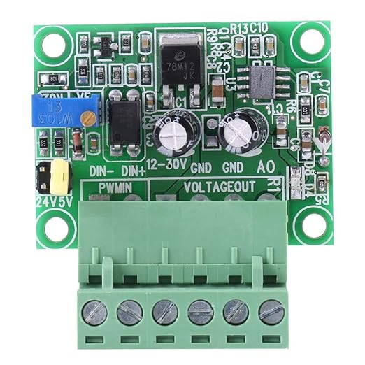
The PWM to 0-10VDC converter board
Laser modulation interface
Although we are using the laser source’s “AD” mode and sending power via a 0-10V analog signal, we wanted to keep the option to use a fast modulation signal if needed. For that we used a MOSFET board from Amazon that provided 0-20KHz PWM switching if we needed it. We are currently using it basically as a relay, but we wanted a very low delay when enabling the laser, and this board provides that.
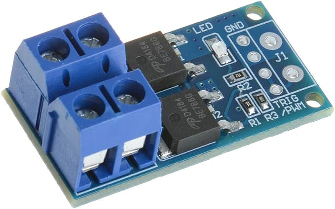
The MOSFET board we used
The light tree
We had some scrapped equipment with a green/orange/red light tree.
We wanted to use that to make it clear when the laser was powered, when it could fire at any time, and when it was firing (or running a program at least). The light tree is powered by 24VDC. The green light is tied straight to the 24V power supply and lights any time the machine is powered on. The orange and red lights are controlled by a 5VDC relay board from Amazon pictured below.

The relay board we used
One advantage of this board is that each relay can be configured to be active high or active low by a jumper. We didn’t end up using this because one Mesa connector was configured to be pullup and one was configured to be pulldown and we could pick and choose our I/O.
The laser enable signal
The laser enable signal is also 24VDC and controlled by one of the relays on the relay board.
Other I/O
We had other “standard CNC” I/O like home switches, estop, and a float switch. I won’t go into detail on those in this article as there are a lot of other places where those are discussed in depth.
The software configuration
LinuxCNC
We started with LinuxCNC 2.9.2 installed via live CD.
PNCConf
We used pncconf for nearly all of our configuration. We applied some configuration customizations after using pncconf. We automated these (described below) so that we could keep the ability to use pncconf to maintain and update the configuration when needed.
Post-pncconf fixes
We want to maintain the ability to update and regenerate the machine configuration using pncconf, but pncconf does not handle every type of customization. So we’ve created a shell script with the Linux sed tool to fix the generated configuration. That script includes “sed” commands (a Linux text manipulation tool) to do a few things:
* Fix a bug in the pncconf-generated config for an unmatched double quote in the loadrt hm2_eth command.
* Add a USER_COMMAND_FILE to the ini file. This file is later used to customize QtPlasmaC.
* As of LinuxCNC 2.9.2, pncconf does not enable setting the filter of the encoder, so we change the “hm2_7i92.0.encoder.00.filter 1” command in the main hal file to be “hm2_7i92.0.encoder.00.filter 0” for reasons described in the capacitive sensor section.
This script must be manually run each time after generating the machine configuration via pncconf.
Customizing QtPlasmaC preferences
Additionally, there are some QtPlasmaC preferences that are intended to be set interactively. Again in our pursuit of maintaining the ability to regenerate the configuration via pncconf we created a script to automate the customizations we want to be made in the . You can see the details of what is customized including the “Arc Voltage Offset”, “Arc Voltage Scale”, “Float Switch Travel”, “Use keyboard shortcuts” “Ohmic probe enable”, and “THC enable”
at github.com/Sector67/fiber-laser-control/...fix-plasmac-prefs.py.
This script was implemented using the same “qtvcp.lib.preferences” ini file library that QtPlasmaC uses. This ensures the changes are made in a way that is consistent with QtPlasmaC, and requires that the script is run using python3. This script must also be run after a pncconf-based configuration is written.
Customizing QtPlasmaC labels and safe height
We additionally wanted to customize a QtPlasmaC label and the safe height. This required using some customization methods that are built into QtPlasmaC. Specifically, if a “qtplasmac_custom.py” file exists in the configuration directory it is processed. This allows customizing nearly all of the QtPlasmaC Python code. As of the writing of this article, we are just changing the “Arc” label. We may implement more customizations in the future.
We also wanted to be able to set a “Safe Height” lower than the default limit of 0.75”. This was slightly complicated since the default value of the “Safe Height” was being set after the qtplasmac_custom.py custom Python code is executed. So in order to set a custom Safe Height we need to use another customization method which requires specifying a “USER_COMMAND_FILE” file in the [DISPLAY] section of the main .ini file. We used “USER_COMMAND_FILE = qtplasmac_custom_post.py”.
Capacitive laser height sensing
Because the amplifier outputs a variable frequency signal, the output of the amp can be treated as an encoder input with the velocity representing the value of the signal. This makes it conceptually similar to a THCAD Mesa device. We are using a Mesa 5i25 board for high speed I/O, and so we can configure a hostmot2 encoder (linuxcnc.org/docs/html/man/man9/hostmot2.9.html#Encoder) via pncconf to read the amp output. Since we are only reading a pulse train and not a quadrature encoder this encoder needs to be in “counter-mode” so that each rising edge of the phase-A input is counted, and the value on phase-B is ignored.
The relatively high frequencies output from the sensor (up to ~3MHz) create some special considerations for interfacing. The Mesa card’s FPGA is fast enough to read the signal, but for the fastest signals of the amps, the “filter” setting of the hostmot2 encoder should be set to “False” since 15 sample clocks at 25MHz is too long to successfully sample a ~3MHz signal. The filter documentation states:
(bit r/w) filter
If set to True (the default), the quadrature counter needs 15 sample clocks to register a change on any of the three input lines (any pulse shorter than this is rejected as noise). If set to False, the quadrature counter needs only 3 clocks to register a change. The default encoder sample clock runs at approximately 25 to 33 MHz but can be changed globally with the sample-frequency or muxed-sample-frequency pin.
The non-default (filter = false) 3 clocks should be fast enough, and with the schmitt trigger the signal is clean enough to work well with a three clock transition. Your custom.hal file will need something like the following:
setp hm2_5i25.0.encoder.00.counter-mode 1
setp hm2_5i25.0.encoder.00.filter 0
With this configuration in place, you can use Halscope or Halmeter to see the “velocity” response of the encoder change with the distance to the metal. The effective response range is around 0.5 inches, with good feedback in the first 0.1 inches off the material.
The output of the encoder velocity from a 0.1” Z move can be seen below:
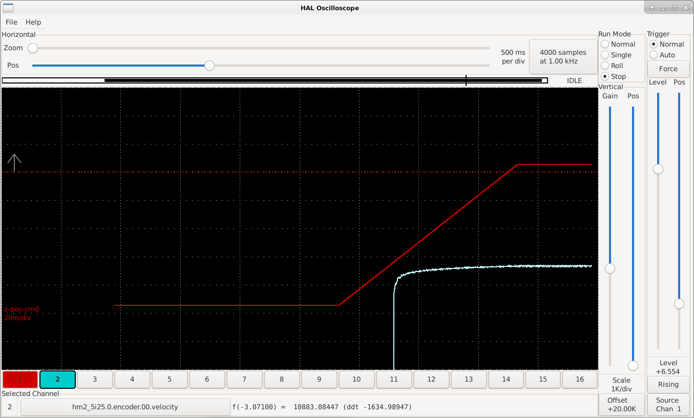
A halscope image of the position and capacitive sensor input
We’ve scaled this value using a combination of the encoder scale and “Arc Voltage Offset” and “Arc Voltage Scale” PLASMA_PARAMETERS. You can see the specific changes in the earlier section on customizing the configuration, but by default the QtPlasmaC GUI does not allow voltage offsets higher than 5 digits, so we use the encoder scale to get the values into a range that can be scaled using PLASMA_PARAMETERS. This could be changed using the qtplasmac_custom_post.py method that we used to change Safe Height, but we already had this workaround in place prior to figuring out how to customize the Safe Height range.
This results in a ~50-100 range for "arc voltage" in the QtPlasmaC GUI and is sensitive enough to hold height well for the cuts that we do. We do customize the GUI to change “Arc” to “CAPACITIVE TORCH HEIGHT” via the qtplasmac_custom.py file.
Fake ohmic probe and arc ok
Since the capacitive sensor output changes dramatically when it touches the part, we were able to implement a synthetic “ohmic probe” using custom hal:
# Make a fake Ohmic probe based on the capacitive sensor
# Use the .velocity-rpm so the .velocity can be left unused for arc_ok
loadrt comp count=1
addf comp.0 servo-thread
net fake-ohmic-probe-in hm2_7i92.0.encoder.00.velocity-rpm comp.0.in0
setp comp.0.in1 930000.0
net plasmac:ohmic-probe comp.0.out
# ohmic output is comp.0.out
We also implemented an “always on” arc ok signal:
# Fake "Arc OK" signal that is always true
loadrt not count=1
addf not.0 servo-thread
setp not.0.in FALSE
net plasmac:arc-ok-in not.0.out
Controlling laser power
The hardware board that converts PWM to 0-10VDC was interfaced to LinuxCNC with the following added to the custom.hal file:
# enable the spindle PWM to drive the laser power
net plasmac:torch-on hm2_7i92.0.pwmgen.00.enable
setp hm2_7i92.0.pwmgen.00.scale 100
net laser-power spindle.0.speed-out-abs hm2_7i92.0.pwmgen.00.value
Additionally, the PWM frequency was configured to be 2000Hz via pncconf and you can see that value reflected in the laser_cutter.hal file:
setp hm2_7i92.0.pwmgen.pwm_frequency 2000
Together these enable a 0-10VDC laser power signal. This will work well for cutting where we are not changing the power frequently. If we want to do raster-style engraving we’d need to switch to using something that does not pause motion when changed. To do that we’d need to switch to using something like M67 as outlined by tommylight at forum.linuxcnc.org/plasma-laser/51727-be...power-with-qtplasmac.
GCode laser power injection
Since we are controlling laser power with spindle speed 0-100 and using the materials “cut amps” to specify the power level for that material, we also need to modify each “M3 $0 S1” line to utilize the material’s cut_amps. The line needs to end up looking like
M03 $0 S#<_hal[qtplasmac.cut_amps-s]>
We achieved this by creating a custom_filter.py that you can see at github.com/Sector67/fiber-laser-control/...fig/custom_filter.py. This has generally worked OK for us so far but might need some refinement as we use different post processors.
Controlling the light tree
The green light of the light tree is simply wired to the +24VDC supply and indicates the machine is powered.
The orange light is intended to indicate that the laser could fire at any time. It is controlled by the following custom hal:
# enable the orange light to represent when the machine is enabled
# and the "torch on" is enabled.
net plasmac:torch-enable and2.0.in0
net machine-is-on and2.0.in1
net orange-light and2.0.out
We sometimes run a program without the torch on to test things, and so it is convenient to see at a glance that the laser will not fire even if the program is started.
The red light indicates that a program is running. If the orange and red lights are both lit then laser may fire at any time. The red light is controlled by the following custom hal:
net plasmac:program-is-running and2.1.in0
net halui-mode-is-auto and2.1.in1
net program-running and2.1.out
net program-running or2.1.in0
net plasmac:program-is-paused or2.1.in1
net program-running-or-paused or2.1.out
…
# enable the red light to represent when the laser is "firing"
# currently defined as when a program is running or the torch is firing
net program-running-or-paused or2.0.in1
net plasmac:torch-on or2.0.in0
net red-light or2.0.out
You can see the full custom.hal file at github.com/Sector67/fiber-laser-control/...in/config/custom.hal.
Gas assist
We are currently using compressed air exclusively, and have implemented a solenoid valve to turn on when a program is running and turn off shortly after. The gas assist is controlled by the following custom hal:
net plasmac:program-is-running and2.1.in0
net halui-mode-is-auto and2.1.in1
net program-running and2.1.out
…
# for now a very naive gas-solenoid control
loadrt timedelay
addf timedelay.0 servo-thread
net program-running timedelay.0.in
setp timedelay.0.on-delay 0.0
setp timedelay.0.off-delay 1.0
net gas-solenoid timedelay.0.out
The gas uses the timedelay component to run for a second after the program ends. This is probably not needed but we’ve left it in place. This timing seems to work well enough as the initial probe takes more than enough time for the gas to get started. If we wanted to turn the torch on and off during a program, we could potentially modify the “arc ok” signal to wait a second for gas to flow before turning the laser on. This would slow things down a bit but if we ever used a gas other than compressed air we may want to conserve it.
The cameras
We wanted to set up a couple of USB cameras to watch the whole table and the laser head itself. We used a cheap endoscope camera for the laser head. We were using a pretty old PC and ran into USB throughput issues, but were able to get small videos for both cameras with the following scripts:
ffplay -i /dev/video0 -x 320 -y 240 -an -window_title "lens camera" -left 1400 -top 100 -video_size 320x240
and
ffplay -i /dev/video2 -x 320 -y 240 -an -window_title "machine camera" -left 1400 -top 400 -video_size 320x240
If you have a more modern PC you could probably run larger video streams. We were then able to run the Linux “SimpleScreenRecorder” tool to capture videos of the whole screen including video streams.
Results and next steps
With this configuration in place we’ve made basic cuts in stainless and mild steel. We still have a bunch of experimentation and tuning to do. The machine cuts 1mm stainless sheet very well, leaving a small burr around the part. We’ve cut up to 0.1” mild steel and expect to be able to cut at least 0.125” with this setup. Our table could be more rigid, so we do currently get some resonance.
You can see one of our very first videos at: , and another video of the laser cutting 1mm stainless steel: .
Building a control system for a 500W Raycus fiber laser using LinuxCNC and QtPlasmaC
Introduction
This document describes a project at Madison, WI USA-based hackerspace Sector67 to create a control system for a Raycus 500 Watt fiber laser cutter using LinuxCNC and QtPlasmaC. This project was basically a proof of concept to work out what would be needed to operationalize a LinuxCNC-controlled fiber laser system. The laser source and head were donated to the space and came to us in an unproven state. There were several challenges that needed to be overcome, but in the end we were able to build a solidly functional fiber laser cutting system.
Many thanks to the Sector67 members that contributed to this project, of course Chris Meyer but also Dave Franchino, Ken Delpapa and many others.
Also many thanks to the dedicated volunteers on the LinuxCNC forums who give of their time freely to foster not only an amazing open source project but also a fantastic open source community. In particular for this project Phillip Carter (phillc54), Tom Berisha (tommylight), Peter Wallace (PCW) and Rod Webster (rodw) were very helpful but there are many others. This project stands on the shoulders of those giants. A lot of this article is summarizing and re-hashing conversations that happened on the LinuxCNC forums.
It is important to mention that fiber lasers will absolutely make you blind in an instant. You must be extremely careful when experimenting with or operating a fiber laser. We surrounded ours with an enclosure and added two cameras to enable operator feedback without needing to put human eyes at risk. The information here is provided to capture our process. If you implement a fiber laser you are proceeding at your own risk and should educate yourself about the real risks of these devices.
The laser cutter
The hardware
The laser source
The laser source for this project was a 500 Watt Raycus C500 “Continuous Wave Fiber Laser”. This laser source has various methods of controlling laser power. For this project we are running it in “AD” mode supplying a 0-10V analog voltage for the laser power, a 24VDC for laser modulation, and 24VDC for laser enable. There is an RS232 serial connection on the device, but we were never able to get more than very rudimentary information from the serial connection.
One important note is that if the LinuxCNC control system is sending a “laser enable” +24VDC signal when the laser source is powered up the laser source will enter a fault mode. In our configuration this signal is enabled when the “machine on” state is entered. We are currently resolving this by powering the laser source first and then enabling the machine. In QtPlasmaC this is the “POWER” button. The laser does send a +24VDC “laser ready” signal on the DB25 connector, and we could in theory use this to prevent entering the “machine on” state unless the laser is powered. However, we currently do a lot of machine testing without the laser on at all, so for now we are just manually working around this with awareness and the specific power on procedure.
The laser head
Our laser head is a “WSX-MN15” model. This manual focus laser head came to us with what should have been a standalone close-loop capacitive height sensor and control board. We could never get that to work properly, which was not a significant problem because from the beginning we wanted to get closed-loop height control controlled by LinuxCNC. So we ended up gutting the on-head capacitive sense and Z height controls and routing the new sensor (described below), home and float sensors, and Z stepper control back to the main control box.
One note is that in addition to everything we stripped off the head, we adapted the air assist to take a ¼” “push to connect” fitting. The threads on the head were G1/8 (BSPP) straight threads, not NPT. It is important to get that right or you may damage the threads on the head and not have an air tight fitting.
The laser head
The capacitive sensor
We used a BCL-AMP capacitive sensor for laser head height sensing. These capacitive sensors are typically used for height sensing in fiber laser cutting systems. The sensors come potted in an aluminum case with a small coax connector to connect to the laser head and a GX16 4-pin circular aviation connector to drive the device. These sensors look like this:
The capacitive amp
There are a number of capacitive sensors with this same basic form factor. We used a “BCL-AMP Amplifier Preamplifier Sensor For Friendess BCS100 Height Controller FSCUT1000 FSCUT2000 System” amp. As of the time this article was written, this amps is available for $52.50 US at www.aliexpress.us/item/3256804585924423.html.
Interfacing the amp to LinuxCNC is described in sections below.
The XY table
The table itself is not really notable. As a prototype platform it has a working area of about 2’x2’ with stepper motor control. It’s not especially fast or rigid unfortunately. There are plenty of other resources for how to get that working with LinuxCNC, so I won’t cover it in too much depth here.
Gas assist
We used a simple 24VDC gas solenoid to control the gas flow. We also implemented a low pressure bypass so that when gas is on there is always some amount of air flowing out of the laser head. This should hopefully prevent any contaminants from getting to the lens when the machine is running.
The electronics of the control system
Mesa card
We’re using a Mesa 7i92TF Anything I/O Ethernet card for I/O. We’re using the G540x2 firmware. We’re using three stepgens for XYZ, one encoder for capacitive sensor input, one PWMgen for 0-10V analog output, and a bunch of I/O. We’re using both the DB25 and 26 pin headers. One advantage of cards like the 7i92 is that you can select via jumper independently if you want the P1 or P2 to be pullup or pulldown. We set the P1 jumper to pulldown which simplified the startup state and the logic and wiring of some components.
Capacitive sensor interface
The functionality of the GX16 4-pin circular aviation connector on the amp seems to be one of the great mysteries of the Internet. As far as we have been able to find, no data sheet or manual for the amp exists, and the circuit diagrams provided by machine integrators do not provide enough detail to determine how to interface with the amp. As a result, we’ve had to reverse engineer the device to determine how to properly interface with it. The results of that experimentation have led us to the following pin functions, with the pins numbered per the GX16 connector spec:
Pin 1, +5V, DC5V DC supplied to the amp
Pin 2, Signal out, A ~5V variable frequency pulse train output
Pin 3, GND, 0V DC supplied to the amp
Pin 4, SHIELD, This is the one pin that you can find conclusively documented on the Internet. This pin should be tied to the cable shield. Internal to the amp, pins 3 and 4 are tied together to the ground plane, with pin 3 going through an RF choke inside the device.
With this hookup and some capacitive input on the small coax connector you can observe a variable-frequency output on pin 2 of the amp. The variable frequency output of the amp is unfortunately not a very clean signal. To clean up this signal we used a SN74HC14N schmitt trigger:
Schmitt trigger pinout
which creates a much cleaner square wave. VCC is wired to +5V and per the data sheet all of the inputs except for one are tied to ground so they don’t float. The output of pin 2 on the amp is wired to one of the trigger inputs, and the output of the trigger is wired to our Mesa 5i25 hostmot2 encoder A-phase input. The SN74HC14N also provides a modest level of signal isolation.
Capacitive frequency response
The following values were measured in a bench setup using a variable capacitor (a radio tuning capacitor wired directly to the amp inputs):
85pF, 2.50MHz
123pF, 2.00MHz
166pF, 1.67MHz
210pF, 1.54MHz
233pF, 1.44MHz
The response is not linear. The closer the metal is to the laser head (the higher the capacitance), the lower the frequency output is. When the head touches the material, the output frequency drops significantly.
0-10V laser power interface
For the 0-10V analog laser power signal we used a frequency to voltage converter from Amazon. This module provides 1-3KHZ 0-10V PWM conversion and basically worked seamlessly with the Mesa PWMgen. Some calibration using the on-board potentiometer was required, and it was not exactly linear, but close enough for our purposes.
The PWM to 0-10VDC converter board
Laser modulation interface
Although we are using the laser source’s “AD” mode and sending power via a 0-10V analog signal, we wanted to keep the option to use a fast modulation signal if needed. For that we used a MOSFET board from Amazon that provided 0-20KHz PWM switching if we needed it. We are currently using it basically as a relay, but we wanted a very low delay when enabling the laser, and this board provides that.
The MOSFET board we used
The light tree
We had some scrapped equipment with a green/orange/red light tree.
We wanted to use that to make it clear when the laser was powered, when it could fire at any time, and when it was firing (or running a program at least). The light tree is powered by 24VDC. The green light is tied straight to the 24V power supply and lights any time the machine is powered on. The orange and red lights are controlled by a 5VDC relay board from Amazon pictured below.
The relay board we used
One advantage of this board is that each relay can be configured to be active high or active low by a jumper. We didn’t end up using this because one Mesa connector was configured to be pullup and one was configured to be pulldown and we could pick and choose our I/O.
The laser enable signal
The laser enable signal is also 24VDC and controlled by one of the relays on the relay board.
Other I/O
We had other “standard CNC” I/O like home switches, estop, and a float switch. I won’t go into detail on those in this article as there are a lot of other places where those are discussed in depth.
The software configuration
LinuxCNC
We started with LinuxCNC 2.9.2 installed via live CD.
PNCConf
We used pncconf for nearly all of our configuration. We applied some configuration customizations after using pncconf. We automated these (described below) so that we could keep the ability to use pncconf to maintain and update the configuration when needed.
Post-pncconf fixes
We want to maintain the ability to update and regenerate the machine configuration using pncconf, but pncconf does not handle every type of customization. So we’ve created a shell script with the Linux sed tool to fix the generated configuration. That script includes “sed” commands (a Linux text manipulation tool) to do a few things:
* Fix a bug in the pncconf-generated config for an unmatched double quote in the loadrt hm2_eth command.
* Add a USER_COMMAND_FILE to the ini file. This file is later used to customize QtPlasmaC.
* As of LinuxCNC 2.9.2, pncconf does not enable setting the filter of the encoder, so we change the “hm2_7i92.0.encoder.00.filter 1” command in the main hal file to be “hm2_7i92.0.encoder.00.filter 0” for reasons described in the capacitive sensor section.
This script must be manually run each time after generating the machine configuration via pncconf.
Customizing QtPlasmaC preferences
Additionally, there are some QtPlasmaC preferences that are intended to be set interactively. Again in our pursuit of maintaining the ability to regenerate the configuration via pncconf we created a script to automate the customizations we want to be made in the . You can see the details of what is customized including the “Arc Voltage Offset”, “Arc Voltage Scale”, “Float Switch Travel”, “Use keyboard shortcuts” “Ohmic probe enable”, and “THC enable”
at github.com/Sector67/fiber-laser-control/...fix-plasmac-prefs.py.
This script was implemented using the same “qtvcp.lib.preferences” ini file library that QtPlasmaC uses. This ensures the changes are made in a way that is consistent with QtPlasmaC, and requires that the script is run using python3. This script must also be run after a pncconf-based configuration is written.
Customizing QtPlasmaC labels and safe height
We additionally wanted to customize a QtPlasmaC label and the safe height. This required using some customization methods that are built into QtPlasmaC. Specifically, if a “qtplasmac_custom.py” file exists in the configuration directory it is processed. This allows customizing nearly all of the QtPlasmaC Python code. As of the writing of this article, we are just changing the “Arc” label. We may implement more customizations in the future.
We also wanted to be able to set a “Safe Height” lower than the default limit of 0.75”. This was slightly complicated since the default value of the “Safe Height” was being set after the qtplasmac_custom.py custom Python code is executed. So in order to set a custom Safe Height we need to use another customization method which requires specifying a “USER_COMMAND_FILE” file in the [DISPLAY] section of the main .ini file. We used “USER_COMMAND_FILE = qtplasmac_custom_post.py”.
Capacitive laser height sensing
Because the amplifier outputs a variable frequency signal, the output of the amp can be treated as an encoder input with the velocity representing the value of the signal. This makes it conceptually similar to a THCAD Mesa device. We are using a Mesa 5i25 board for high speed I/O, and so we can configure a hostmot2 encoder (linuxcnc.org/docs/html/man/man9/hostmot2.9.html#Encoder) via pncconf to read the amp output. Since we are only reading a pulse train and not a quadrature encoder this encoder needs to be in “counter-mode” so that each rising edge of the phase-A input is counted, and the value on phase-B is ignored.
The relatively high frequencies output from the sensor (up to ~3MHz) create some special considerations for interfacing. The Mesa card’s FPGA is fast enough to read the signal, but for the fastest signals of the amps, the “filter” setting of the hostmot2 encoder should be set to “False” since 15 sample clocks at 25MHz is too long to successfully sample a ~3MHz signal. The filter documentation states:
(bit r/w) filter
If set to True (the default), the quadrature counter needs 15 sample clocks to register a change on any of the three input lines (any pulse shorter than this is rejected as noise). If set to False, the quadrature counter needs only 3 clocks to register a change. The default encoder sample clock runs at approximately 25 to 33 MHz but can be changed globally with the sample-frequency or muxed-sample-frequency pin.
The non-default (filter = false) 3 clocks should be fast enough, and with the schmitt trigger the signal is clean enough to work well with a three clock transition. Your custom.hal file will need something like the following:
setp hm2_5i25.0.encoder.00.counter-mode 1
setp hm2_5i25.0.encoder.00.filter 0
With this configuration in place, you can use Halscope or Halmeter to see the “velocity” response of the encoder change with the distance to the metal. The effective response range is around 0.5 inches, with good feedback in the first 0.1 inches off the material.
The output of the encoder velocity from a 0.1” Z move can be seen below:
A halscope image of the position and capacitive sensor input
We’ve scaled this value using a combination of the encoder scale and “Arc Voltage Offset” and “Arc Voltage Scale” PLASMA_PARAMETERS. You can see the specific changes in the earlier section on customizing the configuration, but by default the QtPlasmaC GUI does not allow voltage offsets higher than 5 digits, so we use the encoder scale to get the values into a range that can be scaled using PLASMA_PARAMETERS. This could be changed using the qtplasmac_custom_post.py method that we used to change Safe Height, but we already had this workaround in place prior to figuring out how to customize the Safe Height range.
This results in a ~50-100 range for "arc voltage" in the QtPlasmaC GUI and is sensitive enough to hold height well for the cuts that we do. We do customize the GUI to change “Arc” to “CAPACITIVE TORCH HEIGHT” via the qtplasmac_custom.py file.
Fake ohmic probe and arc ok
Since the capacitive sensor output changes dramatically when it touches the part, we were able to implement a synthetic “ohmic probe” using custom hal:
# Make a fake Ohmic probe based on the capacitive sensor
# Use the .velocity-rpm so the .velocity can be left unused for arc_ok
loadrt comp count=1
addf comp.0 servo-thread
net fake-ohmic-probe-in hm2_7i92.0.encoder.00.velocity-rpm comp.0.in0
setp comp.0.in1 930000.0
net plasmac:ohmic-probe comp.0.out
# ohmic output is comp.0.out
We also implemented an “always on” arc ok signal:
# Fake "Arc OK" signal that is always true
loadrt not count=1
addf not.0 servo-thread
setp not.0.in FALSE
net plasmac:arc-ok-in not.0.out
Controlling laser power
The hardware board that converts PWM to 0-10VDC was interfaced to LinuxCNC with the following added to the custom.hal file:
# enable the spindle PWM to drive the laser power
net plasmac:torch-on hm2_7i92.0.pwmgen.00.enable
setp hm2_7i92.0.pwmgen.00.scale 100
net laser-power spindle.0.speed-out-abs hm2_7i92.0.pwmgen.00.value
Additionally, the PWM frequency was configured to be 2000Hz via pncconf and you can see that value reflected in the laser_cutter.hal file:
setp hm2_7i92.0.pwmgen.pwm_frequency 2000
Together these enable a 0-10VDC laser power signal. This will work well for cutting where we are not changing the power frequently. If we want to do raster-style engraving we’d need to switch to using something that does not pause motion when changed. To do that we’d need to switch to using something like M67 as outlined by tommylight at forum.linuxcnc.org/plasma-laser/51727-be...power-with-qtplasmac.
GCode laser power injection
Since we are controlling laser power with spindle speed 0-100 and using the materials “cut amps” to specify the power level for that material, we also need to modify each “M3 $0 S1” line to utilize the material’s cut_amps. The line needs to end up looking like
M03 $0 S#<_hal[qtplasmac.cut_amps-s]>
We achieved this by creating a custom_filter.py that you can see at github.com/Sector67/fiber-laser-control/...fig/custom_filter.py. This has generally worked OK for us so far but might need some refinement as we use different post processors.
Controlling the light tree
The green light of the light tree is simply wired to the +24VDC supply and indicates the machine is powered.
The orange light is intended to indicate that the laser could fire at any time. It is controlled by the following custom hal:
# enable the orange light to represent when the machine is enabled
# and the "torch on" is enabled.
net plasmac:torch-enable and2.0.in0
net machine-is-on and2.0.in1
net orange-light and2.0.out
We sometimes run a program without the torch on to test things, and so it is convenient to see at a glance that the laser will not fire even if the program is started.
The red light indicates that a program is running. If the orange and red lights are both lit then laser may fire at any time. The red light is controlled by the following custom hal:
net plasmac:program-is-running and2.1.in0
net halui-mode-is-auto and2.1.in1
net program-running and2.1.out
net program-running or2.1.in0
net plasmac:program-is-paused or2.1.in1
net program-running-or-paused or2.1.out
…
# enable the red light to represent when the laser is "firing"
# currently defined as when a program is running or the torch is firing
net program-running-or-paused or2.0.in1
net plasmac:torch-on or2.0.in0
net red-light or2.0.out
You can see the full custom.hal file at github.com/Sector67/fiber-laser-control/...in/config/custom.hal.
Gas assist
We are currently using compressed air exclusively, and have implemented a solenoid valve to turn on when a program is running and turn off shortly after. The gas assist is controlled by the following custom hal:
net plasmac:program-is-running and2.1.in0
net halui-mode-is-auto and2.1.in1
net program-running and2.1.out
…
# for now a very naive gas-solenoid control
loadrt timedelay
addf timedelay.0 servo-thread
net program-running timedelay.0.in
setp timedelay.0.on-delay 0.0
setp timedelay.0.off-delay 1.0
net gas-solenoid timedelay.0.out
The gas uses the timedelay component to run for a second after the program ends. This is probably not needed but we’ve left it in place. This timing seems to work well enough as the initial probe takes more than enough time for the gas to get started. If we wanted to turn the torch on and off during a program, we could potentially modify the “arc ok” signal to wait a second for gas to flow before turning the laser on. This would slow things down a bit but if we ever used a gas other than compressed air we may want to conserve it.
The cameras
We wanted to set up a couple of USB cameras to watch the whole table and the laser head itself. We used a cheap endoscope camera for the laser head. We were using a pretty old PC and ran into USB throughput issues, but were able to get small videos for both cameras with the following scripts:
ffplay -i /dev/video0 -x 320 -y 240 -an -window_title "lens camera" -left 1400 -top 100 -video_size 320x240
and
ffplay -i /dev/video2 -x 320 -y 240 -an -window_title "machine camera" -left 1400 -top 400 -video_size 320x240
If you have a more modern PC you could probably run larger video streams. We were then able to run the Linux “SimpleScreenRecorder” tool to capture videos of the whole screen including video streams.
Results and next steps
With this configuration in place we’ve made basic cuts in stainless and mild steel. We still have a bunch of experimentation and tuning to do. The machine cuts 1mm stainless sheet very well, leaving a small burr around the part. We’ve cut up to 0.1” mild steel and expect to be able to cut at least 0.125” with this setup. Our table could be more rigid, so we do currently get some resonance.
You can see one of our very first videos at: , and another video of the laser cutting 1mm stainless steel: .

08 May 2024 12:03
If you have an arcOK signal built in to your plasma (Which you have) I recommend mode 1. Using Synthesised ArcOK can create spurious signals that can cause the symptoms you describe if not set up correctly.
Specifically, on piercing, the voltage does not climb constantly. It often dips down. If the ArcOK has been enabled this can be sensed as a loss of ArcOK (Although I believe QTPlasmac has some settings now that are supposed to work around this).
Its much better and safer to rely on what the plasma cutter is telling you than guessing no matter how smart the guessing algorithim is....
Replied by rodw on topic No Juice, well there is for a Split second
No Juice, well there is for a Split second
Category: Plasmac
Which leads me to query why the mode is missing from your ini file?I am set to Mode 1 for qtplasmac so wondering if with the THCAD2 do I really need the arc ok in signal?
If you have an arcOK signal built in to your plasma (Which you have) I recommend mode 1. Using Synthesised ArcOK can create spurious signals that can cause the symptoms you describe if not set up correctly.
Specifically, on piercing, the voltage does not climb constantly. It often dips down. If the ArcOK has been enabled this can be sensed as a loss of ArcOK (Although I believe QTPlasmac has some settings now that are supposed to work around this).
Its much better and safer to rely on what the plasma cutter is telling you than guessing no matter how smart the guessing algorithim is....
08 May 2024 10:03
Replied by FlaredFins on topic No Juice, well there is for a Split second
No Juice, well there is for a Split second
Category: Plasmac
Up early this morning to get back at this and while in qtplasmac I don't have the arc ok light lit on screen, but it is signaling Plasmac.arc.ok.in. So not sure if this is creating issues. I am set to Mode 1 for qtplasmac so wondering if with the THCAD2 do I really need the arc ok in signal?
07 May 2024 13:52 - 07 May 2024 13:54
Replied by keryboros on topic THCAD-5 source? {reasonable shipping to UK}
THCAD-5 source? {reasonable shipping to UK}
Category: User Exchange
Very expensive prices, so I advise you to use such services as www.pirateship.com/ (you can also look at such service as sendle and compare prices with pirateship and shipping to a particular country)
or I suggest you just buy a couple of shipping labels through labels.vs (the purchase function opens after registration).
andypugh, parcelmonkey compared to pirateship or sendle is also an expensive service")
or I suggest you just buy a couple of shipping labels through labels.vs (the purchase function opens after registration).
andypugh, parcelmonkey compared to pirateship or sendle is also an expensive service

07 May 2024 13:45
Replied by tommylight on topic The blacksmith's plasma table
The blacksmith's plasma table
Category: Plasma & Laser
In this case, it acts as a dead short for the AC interference while the HV start/pilot is on, it does not affect the DC voltage that THCAD needs to measure.
07 May 2024 10:00
While I greatly appreciate all your advice, it bother me to not understand why I'm adding a capacitor. Would you have some ressources where I can learn what this capacitor does in this case ? I tried to look it up but I dont even know where to start, there is so much information.
Does the capacitor act as some kind of "electronic spring" to absorb a HV surge ? And how did you know which capacity and voltage it should have ?
Replied by polskleforgeron on topic The blacksmith's plasma table
The blacksmith's plasma table
Category: Plasma & Laser
Nope, that is 1uF, you need 0.1uF or 100nF
It does not mater much where, but i would still place the capacitor at the THCAD input, resistors inside the plasma.
Not a DC capacitor nor electrolytic one, metal film have no polarity and are good ad reducing interference.
While I greatly appreciate all your advice, it bother me to not understand why I'm adding a capacitor. Would you have some ressources where I can learn what this capacitor does in this case ? I tried to look it up but I dont even know where to start, there is so much information.
Does the capacitor act as some kind of "electronic spring" to absorb a HV surge ? And how did you know which capacity and voltage it should have ?
06 May 2024 16:59
Replied by tommylight on topic The blacksmith's plasma table
The blacksmith's plasma table
Category: Plasma & Laser
Nope, that is 1uF, you need 0.1uF or 100nF
It does not mater much where, but i would still place the capacitor at the THCAD input, resistors inside the plasma.
Not a DC capacitor nor electrolytic one, metal film have no polarity and are good ad reducing interference.
It does not mater much where, but i would still place the capacitor at the THCAD input, resistors inside the plasma.
Not a DC capacitor nor electrolytic one, metal film have no polarity and are good ad reducing interference.
06 May 2024 14:07
Also dumb question, I can easily fin some 300V AC 0.1uF capacitors. But we're talking DC here right ? Is it still OK or should I find a specific DC one ? I remember something about electrolytic capacitors that can only be use in DC..
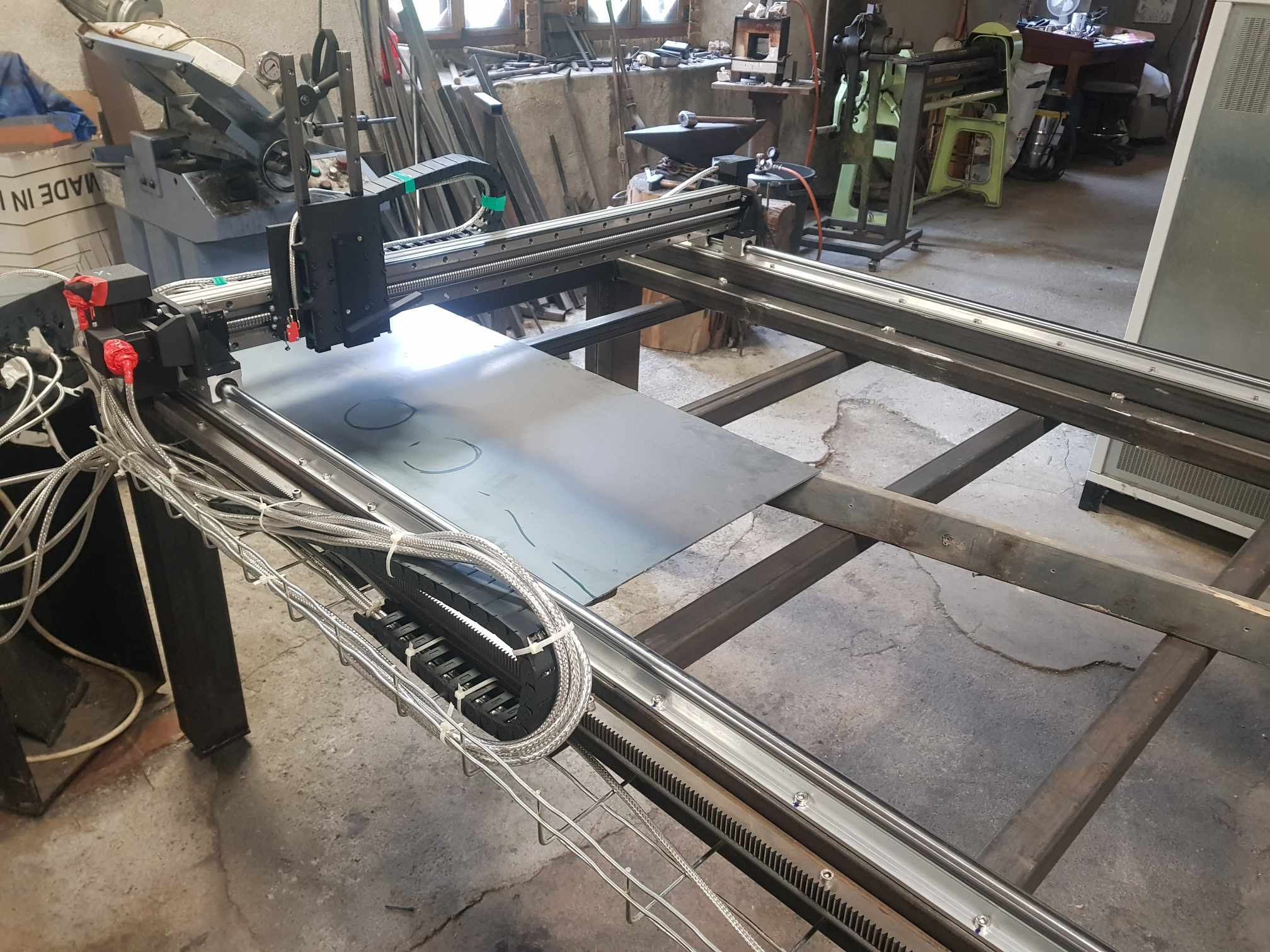
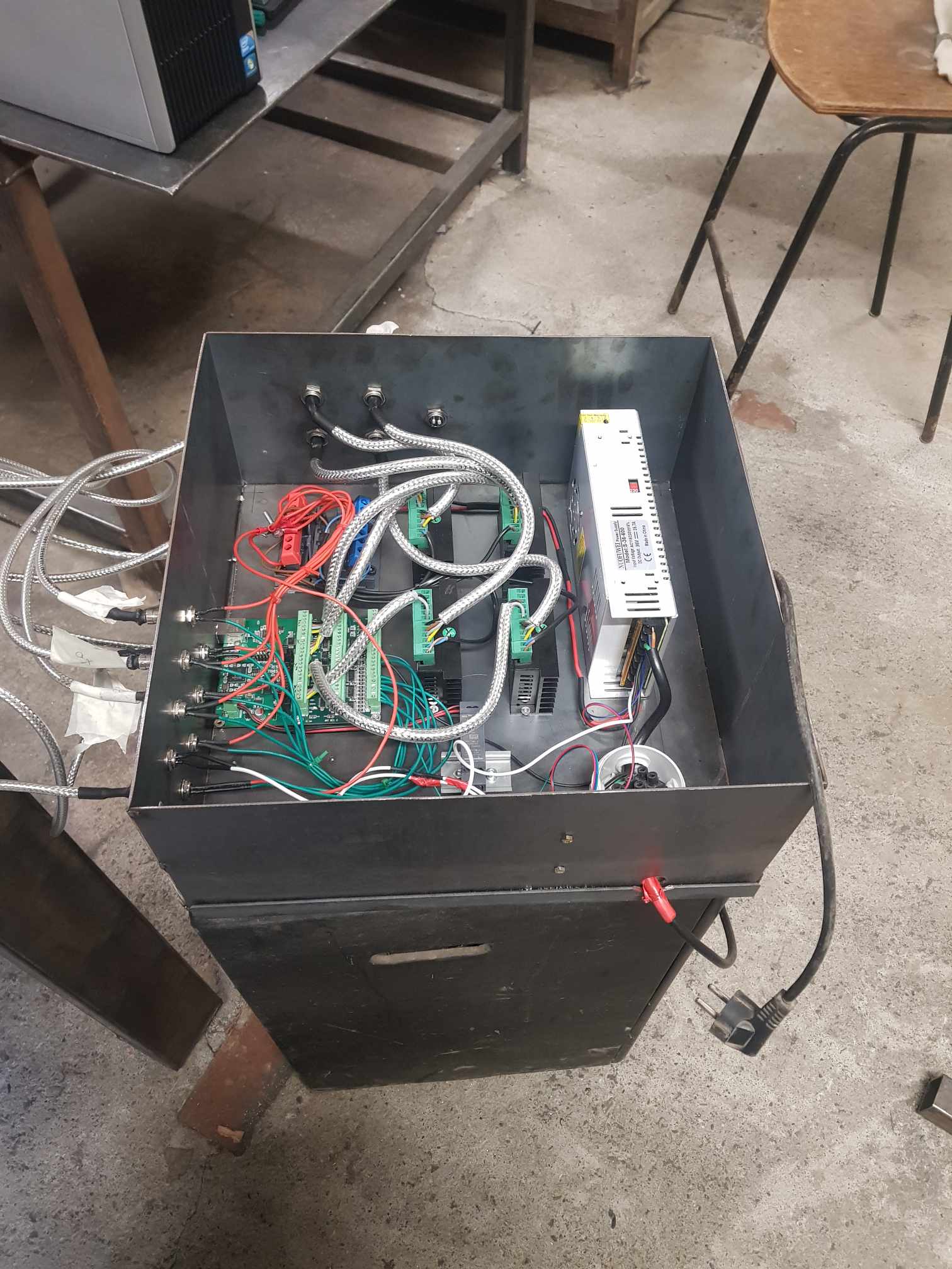
Some pictures of the project !
Replied by polskleforgeron on topic The blacksmith's plasma table
The blacksmith's plasma table
Category: Plasma & Laser
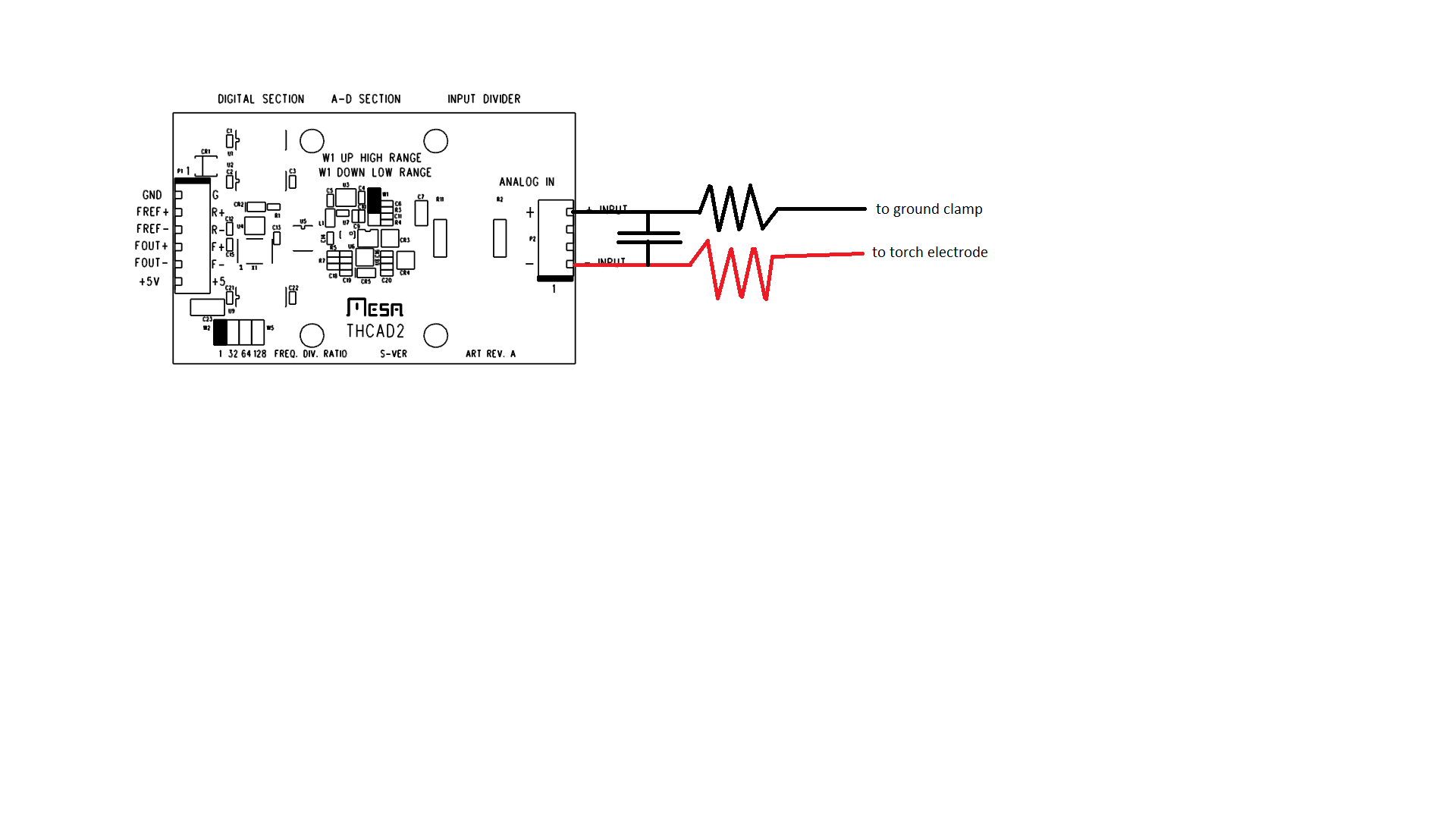
Is it better to add the resistors and capacitors closer to the THCAD-2 or the connexion in the plasma cutter ? I feel like it would be better at the source, inside the frame of the plasma.
Also when you say you plugged the cheap china plasma through 2 resistors (both 1MO 2W) with a capacitor (0.1uF and what power rating ?) shorting the two, would it look like that :
Exactly !
Capacitors have no power rating, just capacity and voltage, sometimes temperature range in a form of a single letter. Anything from 300-500V will do just fine.
Also dumb question, I can easily fin some 300V AC 0.1uF capacitors. But we're talking DC here right ? Is it still OK or should I find a specific DC one ? I remember something about electrolytic capacitors that can only be use in DC..
Some pictures of the project !
06 May 2024 10:14 - 06 May 2024 11:55
When you say "just some care must be taken when wiring to choose a suitable point where the HF has less effect, usually at the rectifier output or at the built in HF filter/protection", do you mean that I shouldn't take the arc voltage the "simple" way from the ground clamp to the torch electrode, but instead get the wiring inside the Plasma cutter ? I think maybe I can do that..
Also when you say you plugged the cheap china plasma through 2 resistors (both 1MO 2W) with a capacitor (0.1uF and what power rating ?) shorting the two, would it look like that :
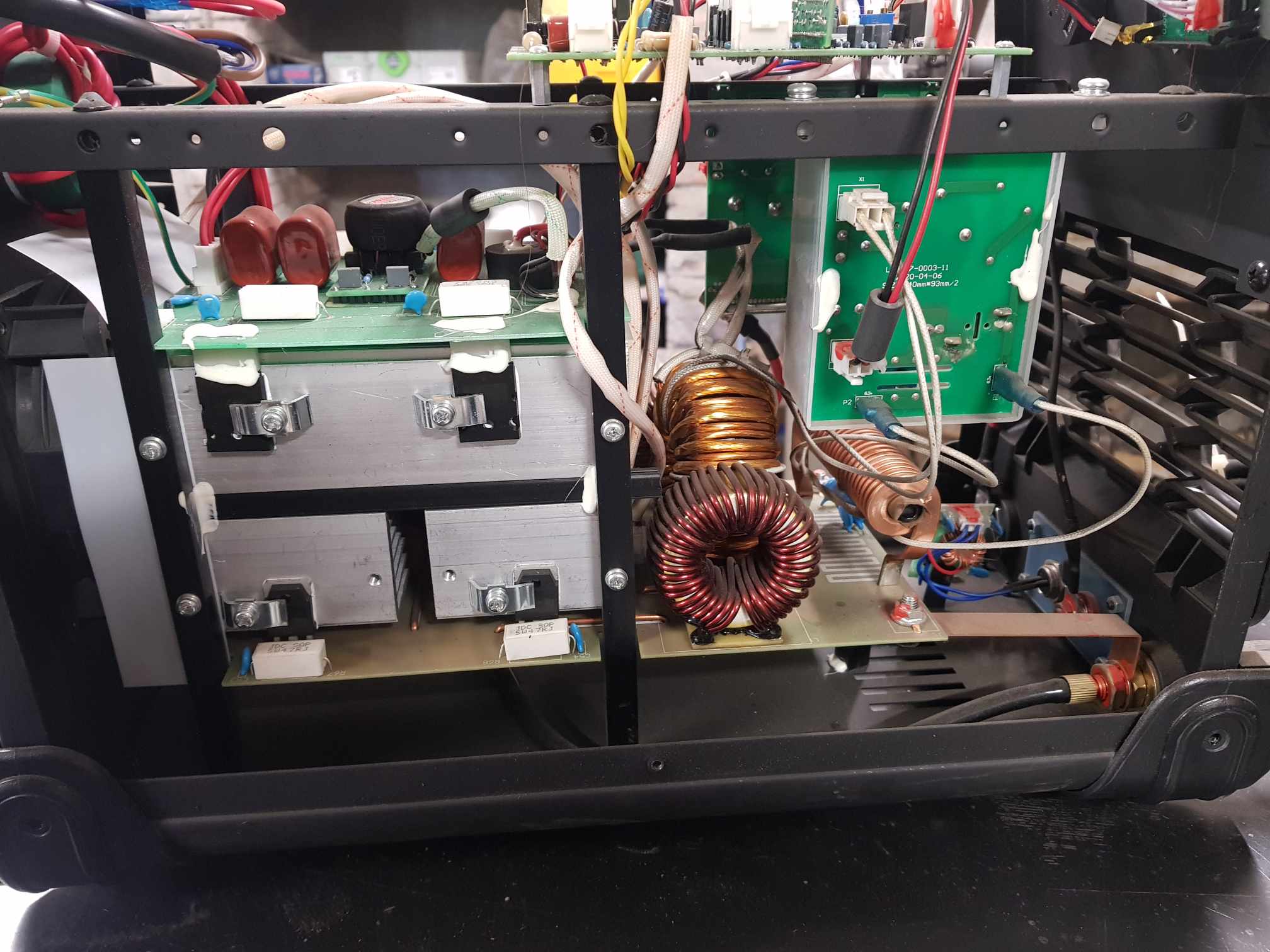
I've added some pictures of the plasma's cutter inside :
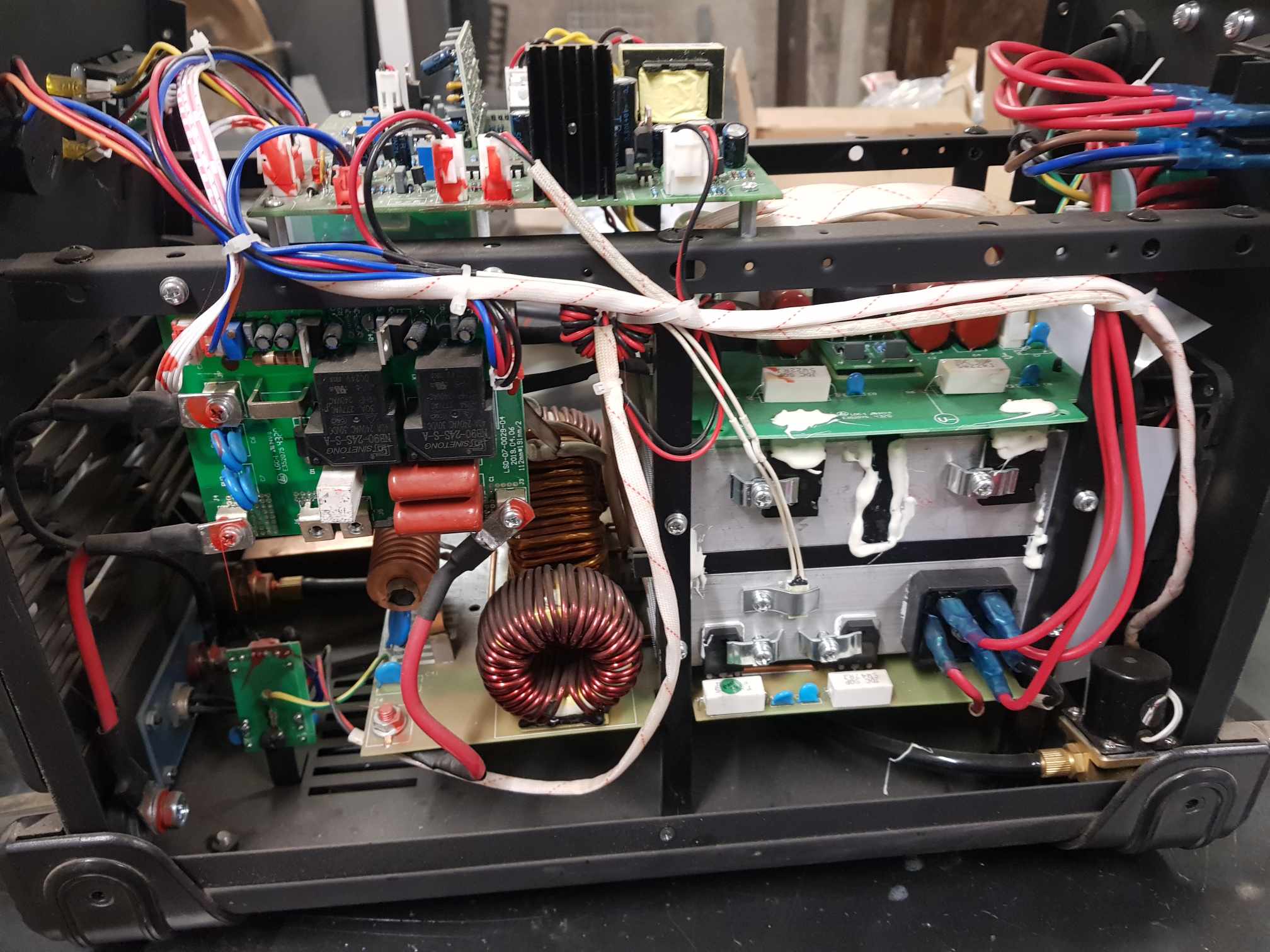
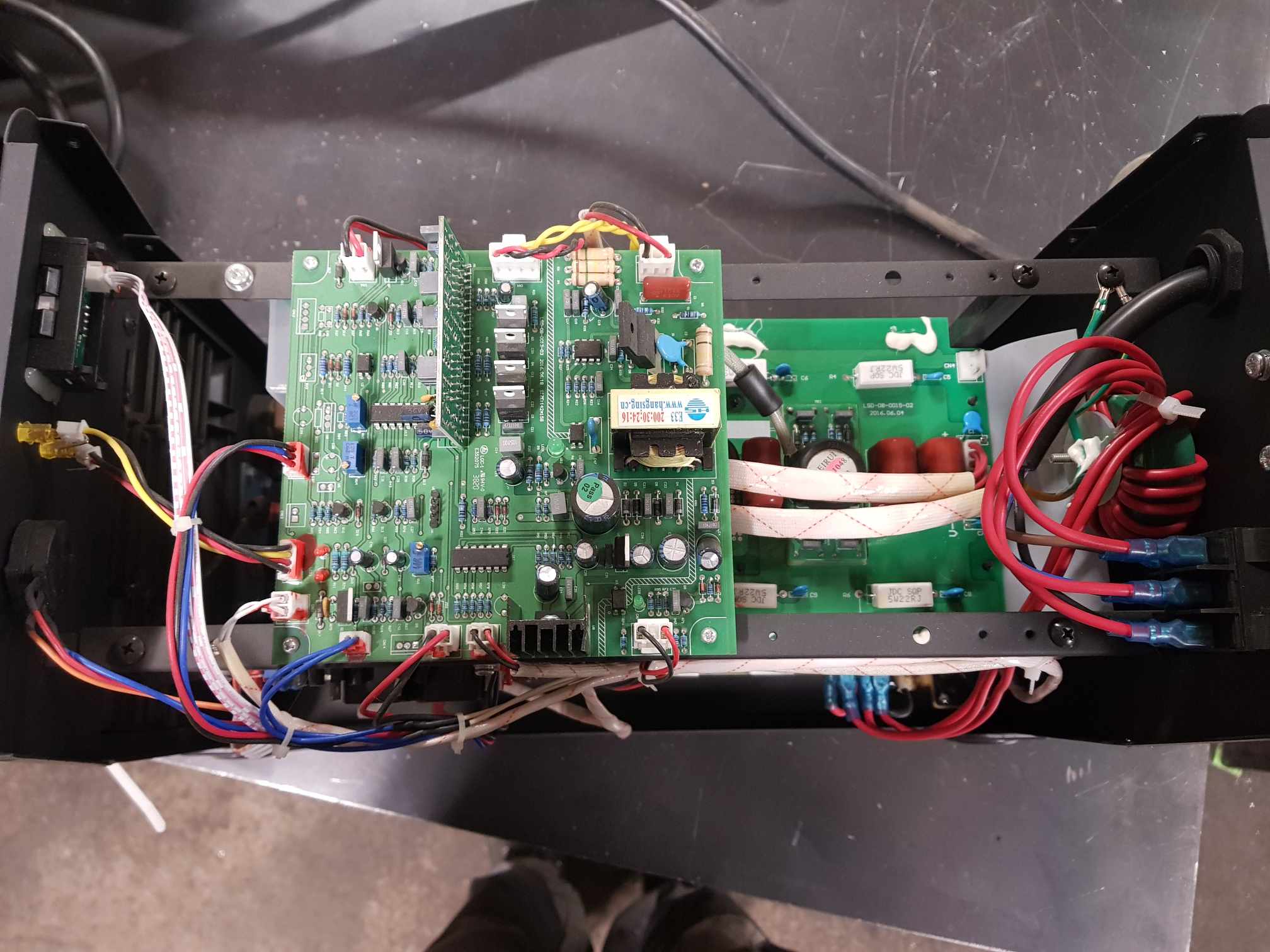
Replied by polskleforgeron on topic The blacksmith's plasma table
The blacksmith's plasma table
Category: Plasma & Laser
Thank you again for your explanation, but it's a bit technical for me and I'm not sure to understand.@Rod,
He mentioned several times he has a HF/HV start plasma, the THCAD manual clearly states not to use that combo.
Having cleared that cautionary tale, THCAD can work with HF/HV start as can be proven by probably 10 i have in use daily, just some care must be taken when wiring to choose a suitable point where the HF has less effect, usually at the rectifier output or at the built in HF filter/protection.
And additionally a few days back i wired a THCAD10 directly to outside connectors on a new cheap china inverter plasma with HF start, THROUGH 2 resistors and added a 0.22uF/350V capacitor across the THCAD input just to be on the safe side, and it also filters the readings a bit. Used it for 2 days, all good, probably did over 200 starts as i was tuning voltage/feed/air so made a lot of 100x10mm rectangles.
Just to be clear, do this at your own risk, any mishaps usually end badly.
A 0.1uF capacitor would be better, did not have one with such high voltage.
When you say "just some care must be taken when wiring to choose a suitable point where the HF has less effect, usually at the rectifier output or at the built in HF filter/protection", do you mean that I shouldn't take the arc voltage the "simple" way from the ground clamp to the torch electrode, but instead get the wiring inside the Plasma cutter ? I think maybe I can do that..
Also when you say you plugged the cheap china plasma through 2 resistors (both 1MO 2W) with a capacitor (0.1uF and what power rating ?) shorting the two, would it look like that :
I've added some pictures of the plasma's cutter inside :
06 May 2024 01:18
Replied by tommylight on topic The blacksmith's plasma table
The blacksmith's plasma table
Category: Plasma & Laser
OP has a choice between a HF start and a HF start with CPC port.
I worked with Stamos, it works fine, Stahlwerk before it also worked fine, meaning over a year of use for each, none of them mine personally.
Now under the covers, there were two reasons i did the last deed:
-New plasma under warranty, cheap Kzubr for 320 Euro, 60A, so could not open it.
-I had a THCAD collecting dust, so i risked it, it survived unscathed!
I was pretty sure it would work as i did add a capacitor across the THCAD input to short whatever HF gets to it and after the resistor drop should not be much to deal with, but the biggest surprise was it actually does 60A flat! That is in both 220V and 380V, and that raises a worrying question: what happens when someone less experienced gets it and plugs it into 220V and starts using it drawing over 30A from the mains! We (Europe) has a limit of 16A for anything 220V, so that will melt the plugs in a very short time.
380V is all good as it does roughly 18-19A, and we can do 16 or 32A depending on the socket size, probably should be fine with the small socket as it mostly will cut with 40-45A.
Again under the covers, i am mentioning all this as it applies to this topic, the plasma sources are all the same.

05 May 2024 22:40
Replied by djonz on topic 7i96S + 7i85S + THCAD2 firmware?
7i96S + 7i85S + THCAD2 firmware?
Category: Driver Boards
Wow that was fast!
Many thanks to you, really appreciate the work.
Have a great day!
Many thanks to you, really appreciate the work.
Have a great day!
05 May 2024 22:26
Replied by FlaredFins on topic THCad2 Meter question
THCad2 Meter question
Category: Driver Boards
Lol Ok I had just switched it back to 1.
Also is there anything else that needs to be looked at before I actually fire the torch? I know there were some changes needed for the other car with OHMIC sense but cant remember if there were files that need to added into HAL or the Ini. I set it up through PNCconf. just need to go back and set it for 32 again
Also is there anything else that needs to be looked at before I actually fire the torch? I know there were some changes needed for the other car with OHMIC sense but cant remember if there were files that need to added into HAL or the Ini. I set it up through PNCconf. just need to go back and set it for 32 again
05 May 2024 22:20
05 May 2024 21:49
Replied by FlaredFins on topic THCad2 Meter question
THCad2 Meter question
Category: Driver Boards
What divider ratio do you use on the THCad2 1, 32, 64, 128?

05 May 2024 20:18
Replied by PCW on topic 7i96S + 7i85S + THCAD2 firmware?
7i96S + 7i85S + THCAD2 firmware?
Category: Driver Boards
7I96S+7I85S plasma config:
Note that because of the use of muxed encoders, the on 7I96S encoders
are numbered oddly = 4,6,8
The 7i96s_7i85sd.pin file in the distribution is incorrect, but the
7i96s_7i85sd.bin file is OK (it has the INM on the TB3 pins)
Note that you _can_ still use the 7I96/7i96s TB3 inputs without the INM
(GPIO works). There are be 7I96 configurations without the INM
but the 7I96S's larger FPGA means it should always fit
Time to create page: 1.719 seconds