Problem with toolpath and machining limits
- bruno2626
- Offline
- Senior Member
-

Less
More
- Posts: 50
- Thank you received: 3
28 Sep 2020 08:52 - 28 Sep 2020 14:46 #184123
by bruno2626
Problem with toolpath and machining limits was created by bruno2626
Hi,
After fixing other problems and upgrading to LCNC 2.8, I come back with my machining limits problem.
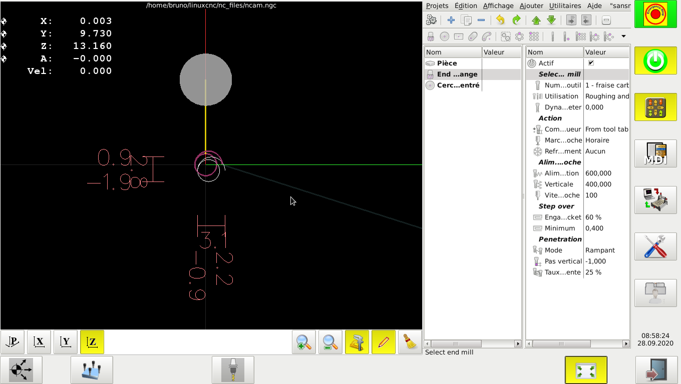
Here is what I get (a simple spiral drilling with nativecam normally oriented at x0 y0):
The planned toolpath is shifted by a somewhat random value. The real toolpath is in the right place. I don't have this problem with axis display.
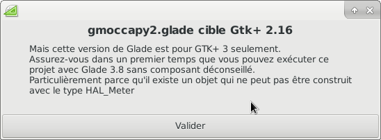
Can this have something to do with a gladevcp problem? This is what I get if I try to open gmoccapy2.glade:
Thanks.
Attachments:
Last edit: 28 Sep 2020 14:46 by bruno2626.
Please Log in or Create an account to join the conversation.
- bruno2626
- Offline
- Senior Member
-

Less
More
- Posts: 50
- Thank you received: 3
29 Sep 2020 07:29 #184249
by bruno2626
Replied by bruno2626 on topic Problem with toolpath and machining limits
Hi,
Are there any internal variables I can check? Maybe by setting debug=1 in the ini file?
Are there any internal variables I can check? Maybe by setting debug=1 in the ini file?
Please Log in or Create an account to join the conversation.
- newbynobi
-

- Offline
- Moderator
-

Less
More
- Posts: 1930
- Thank you received: 394
29 Sep 2020 16:01 #184305
by newbynobi
Replied by newbynobi on topic Problem with toolpath and machining limits
You can not open the glade2 file, cause you have glade3 installed, not glade 2. We are working on a glade3 and python3 release, but this will take some time.
The displacement is know, it is just a grafical issue, due to rounding numbers and inaxecat maths in glemlin view. I looked at this a while ago and was not able to fix it. I will not put any affort in fixing that, because of working on a python3 release together with other developers.
just to check, if your offsets of g54 are at a exact value, like 15.000 or 120.000 the displacement should not be visible. Is that right?
If not, I will need to look at this.
Hope I got your understanding for the inconvinience.
Norbert
The following user(s) said Thank You: Aciera
Please Log in or Create an account to join the conversation.
- bruno2626
- Offline
- Senior Member
-

Less
More
- Posts: 50
- Thank you received: 3
30 Sep 2020 06:20 #184356
by bruno2626
Replied by bruno2626 on topic Problem with toolpath and machining limits
Hi newbynobi,
Thank you for your response. It makes me feel a little reassured, I thought I was the only one with this problem!
Concerning the x and y shift, it seems to be that, I find in the shift the decimals of g54. However, I don't understand why g54 offsets are included in the calculation of machining limits. For my culture and because I am curious, where is the calculation of these limits done? In which file? This calculation is different with axis?
On the other hand in Z, the limit is sometimes in red, therefore out of the frame, whereas in reality the course is well within the frame and that in manual I can reach these coordinates with a lot of margin.
I need to use the machine more. I haven't yet fully understood how to use G43 with gmoccapy. I remapped the M6 function for the automatic tool changer, and in my toolchange.ngc file I put G49 at the beginning and G43 at the end to make sure that at each tool change the tool length is taken into account. Is this a good idea? Sometimes it goes back to G49 without my asking, I don't know why.
Bruno.
Please Log in or Create an account to join the conversation.
- newbynobi
-

- Offline
- Moderator
-

Less
More
- Posts: 1930
- Thank you received: 394
30 Sep 2020 20:40 #184418
by newbynobi
Replied by newbynobi on topic Problem with toolpath and machining limits
You need to take G54 offsets to the calculation.
Just imagine you put G54 to Absolut 10 10 10, so you are 10 mm away from Machine limits.
Now try to mill a circle with 100 mm diameter with center to be G54 0 0 0.
This would pass your limits!
I have not found a single file, but a bunch of not documented files. If you like, just begin to look at /lib/python/gladevcp/gremlin.py
As me and other developers are working on the shift to python3, I would not invest any time to fix a cosmetic bug. Gremlin need to be rewrite completely to be adapted to python3, that would hopefully also fix the misbehavior you see.
Norbert
Please Log in or Create an account to join the conversation.
- bruno2626
- Offline
- Senior Member
-

Less
More
- Posts: 50
- Thank you received: 3
01 Oct 2020 06:16 #184453
by bruno2626
Replied by bruno2626 on topic Problem with toolpath and machining limits
Hi,
To check that the machining will be within the machine limits, I agree that G54 must be taken into account to have machine coordinates, but to display the toolpath limits in relative coordinates it is "only" necessary to read the gcode.
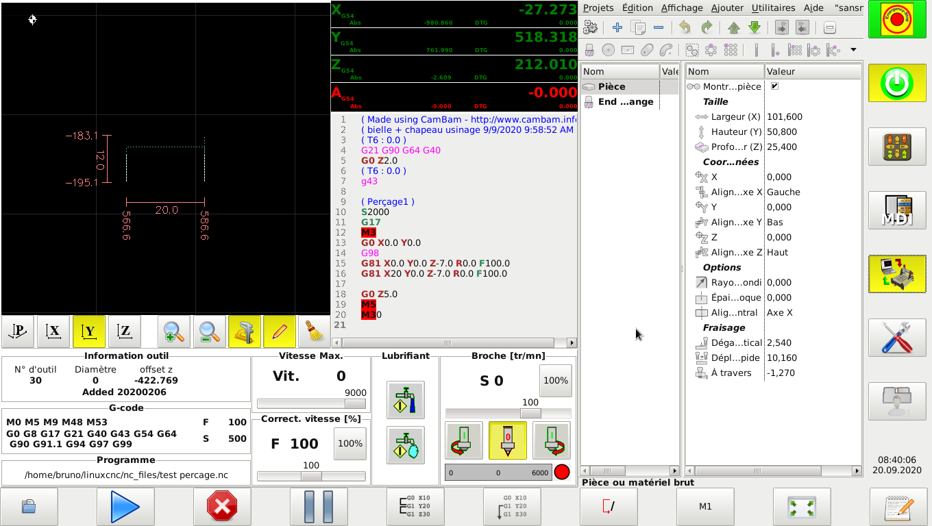
By dint of playing with gmoccapy and g54, I had managed to make it bug more than a few decimals. Look at this screenshot :
The displayed limits look more like machine coordinates. I have the impression that the limits are calculated according to "gcode" + g54 - g54, except here where there is only half of the calculation in fact.
Thanks for the location of the file, I'll take a look at it to learn.
Bruno
Please Log in or Create an account to join the conversation.
Moderators: newbynobi, HansU
Time to create page: 0.688 seconds


