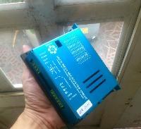
Frequency to voltage for pathpilot spindle control
- tivoi
-
 Topic Author
- Offline
- Senior Member
-

Less
More
- Posts: 66
- Thank you received: 20
09 Dec 2017 04:14 #102809
by tivoi
Frequency to voltage for pathpilot spindle control was created by tivoi
Please Log in or Create an account to join the conversation.
- Rhine_Labs
-

- Offline
- Senior Member
-

Less
More
- Posts: 79
- Thank you received: 11
11 Dec 2017 03:04 #102890
by Rhine_Labs
Replied by Rhine_Labs on topic Frequency to voltage for pathpilot spindle control
I wonder what type of circuit they are using on the lathe door and limit switches?
# used to decode the signal from the lathe control board that encodes
# the door and limit switches as a frequency
# used to decode the signal from the lathe control board that encodes
# the door and limit switches as a frequency
Please Log in or Create an account to join the conversation.
- tivoi
-
 Topic Author
- Offline
- Senior Member
-

Less
More
- Posts: 66
- Thank you received: 20
11 Dec 2017 03:14 #102891
by tivoi
Replied by tivoi on topic Frequency to voltage for pathpilot spindle control
Please Log in or Create an account to join the conversation.
- tivoi
-
 Topic Author
- Offline
- Senior Member
-

Less
More
- Posts: 66
- Thank you received: 20
11 Dec 2017 03:31 #102893
by tivoi
Replied by tivoi on topic Frequency to voltage for pathpilot spindle control
Please Log in or Create an account to join the conversation.
- tivoi
-
 Topic Author
- Offline
- Senior Member
-

Less
More
- Posts: 66
- Thank you received: 20
11 Dec 2017 03:33 #102894
by tivoi
i think we need MCU, arduino can cover that prolem
Replied by tivoi on topic Frequency to voltage for pathpilot spindle control
I wonder what type of circuit they are using on the lathe door and limit switches?
# used to decode the signal from the lathe control board that encodes
# the door and limit switches as a frequency
i think we need MCU, arduino can cover that prolem
Please Log in or Create an account to join the conversation.
- smgvbest
-

- Offline
- Elite Member
-

Less
More
- Posts: 311
- Thank you received: 51
11 Dec 2017 04:08 #102895
by smgvbest
Replied by smgvbest on topic Frequency to voltage for pathpilot spindle control
They use a MCU on board. I believe it was a atmel which would infer arduino and if so it's a simple thing to read the inputs and generate a tone (arduino libraries for that are built in) given the separation in the tones it's pretty easy to do actually.
But even with a PIC this is easy to do IMHO
But even with a PIC this is easy to do IMHO
Please Log in or Create an account to join the conversation.
- tivoi
-
 Topic Author
- Offline
- Senior Member
-

Less
More
- Posts: 66
- Thank you received: 20
11 Dec 2017 05:28 #102896
by tivoi
hi smgvbest
did you check frequency, i thik we can do it with arduino
Replied by tivoi on topic Frequency to voltage for pathpilot spindle control
They use a MCU on board. I believe it was a atmel which would infer arduino and if so it's a simple thing to read the inputs and generate a tone (arduino libraries for that are built in) given the separation in the tones it's pretty easy to do actually.
But even with a PIC this is easy to do IMHO
hi smgvbest
did you check frequency, i thik we can do it with arduino
Please Log in or Create an account to join the conversation.
- PCW
-

- Away
- Moderator
-

Less
More
- Posts: 17450
- Thank you received: 5091
11 Dec 2017 17:22 - 11 Dec 2017 17:33 #102910
by PCW
Replied by PCW on topic Frequency to voltage for pathpilot spindle control
Why would you do that? Unless you are using a Tormach breakout board, its easier to just use PWM for the VFD
and get additional inputs from another port
and get additional inputs from another port
Last edit: 11 Dec 2017 17:33 by PCW.
The following user(s) said Thank You: tivoi
Please Log in or Create an account to join the conversation.
- tivoi
-
 Topic Author
- Offline
- Senior Member
-

Less
More
- Posts: 66
- Thank you received: 20
12 Dec 2017 01:50 #102963
by tivoi
i was make new bit file, changle step to pwm for spindle, but i have prolem with hal file, can you help me check it?
########################################################################
# Spindle speed control
#
# stepgen outputs the frequency it is told by tormachspindle comp
#
# type 1 velocity control mode
#setp hm2_5i25.0.stepgen.04.control-type 1
# step/dir
# type 2 quadrature output for 50% duty cycle
#setp hm2_5i25.0.stepgen.04.step_type 2
# no scaling 1:1
#setp hm2_5i25.0.stepgen.04.position-scale 0.5
# handle spindle at speed via separate component
#setp hm2_5i25.0.stepgen.04.maxaccel 0
# stepspace in nanoseconds
#setp hm2_5i25.0.stepgen.04.stepspace 0
# steplen in nanoseconds (10 microseconds)
#setp hm2_5i25.0.stepgen.04.steplen 10000
# assume standard spindle until UI sets it
setp tormachspindle.spindle-type 0
# hispeed spindle min/max
setp tormachspindle.hispeed-min 6000
setp tormachspindle.hispeed-max 24000
# allow UI to access min/max for high speed spindle
# do not net these until the UI code is changed to set them explicitly
# or the setp command above will not stick and they will be set to 0
net spindle-hispeed-min tormachspindle.hispeed-min
net spindle-hispeed-max tormachspindle.hispeed-max
# these let the UI read the min/max maintained by the comp based on spindle type
net spindle-min-speed tormachspindle.min-speed
net spindle-max-speed tormachspindle.max-speed
# the UI sets the spindle type
net spindle-type tormachspindle.spindle-type
# assume high range until UI sets it
setp tormachspindle.belt-position 1
net spindle-range tormachspindle.belt-position
net spindle-range-alarm tormachspindle.speed-alarm
setp tormachspindle.lowbelt-min-rpm [SPINDLE]LO_RANGE_MIN
setp tormachspindle.lowbelt-max-rpm [SPINDLE]LO_RANGE_MAX
setp tormachspindle.highbelt-min-rpm [SPINDLE]HI_RANGE_MIN
setp tormachspindle.highbelt-max-rpm [SPINDLE]HI_RANGE_MAX
# frequencies sent to stepgen to achieve low belt speeds
# 500 Hz -> 6 Hz at VFD -> 175 RPM at spindle (770)
# 10900 Hz -> 120 Hz at VFD -> 3250 RPM at spindle (770)
# 500 Hz -> 6 Hz at VFD -> 100 RPM at spindle (1100-2-3)
# 10900 Hz -> 120 Hz at VFD -> 2000 RPM at spindle (1100-2-3)
# 1600 Hz -> 300 RPM at spindle (1100-1)
# 10900 Hz -> 1750 RPM at spindle (1100-1)
setp tormachspindle.lowbelt-min-mcb-freq [SPINDLE]MIN_MCB_FREQUENCY
setp tormachspindle.lowbelt-max-mcb-freq [SPINDLE]MAX_MCB_FREQUENCY
# frequencies sent to stepgen to achieve high belt speeds
# 500 Hz -> 6 Hz at VFD -> 525 RPM at spindle (770)
# 10900 Hz -> 120 Hz at VFD -> 10200 RPM at spindle (770)
# 500 Hz -> 6 Hz at VFD -> 250 RPM at spindle (1100-2-3)
# 10900 Hz -> 120 Hz at VFD -> 5140 RPM at spindle (1100-2-3)
# 1600 Hz -> 800 RPM at spindle (1100-1)
# 10900 Hz -> 4500 RPM at spindle (1100-1)
setp tormachspindle.highbelt-min-mcb-freq [SPINDLE]MIN_MCB_FREQUENCY
setp tormachspindle.highbelt-max-mcb-freq [SPINDLE]MAX_MCB_FREQUENCY
# speed-out is displayed by UI when program running
net spindle-speed-fb-rpm tormachspindle.speed-out
# connect motion speed-out to input of spindle comp
net spindle-speed-raw motion.spindle-speed-out tormachspindle.speed-in
# connect output of spindle comp to stepgen
#net spindle-speed tormachspindle.mcb-freq-out hm2_5i25.0.stepgen.04.velocity-cmd
setp hm2_5i25.0.pwmgen.01.output-type 1
setp hm2_5i25.0.pwmgen.01.pwm_frequency 24000
setp hm2_5i25.0.pwmgen.01.scale 100
net spindle-speed tormachspindle.mcb-freq-out hm2_5i25.0.pwmgen.01.value
# spindle at speed parameters for tormachspindle component
setp tormachspindle.startup-delay [SPINDLE]STARTUP_DELAY
# time to reach max speed from stopped
setp tormachspindle.seconds-to-max-rpm [SPINDLE]SECONDS_TO_MAX_RPM
# connect spindle comp at-speed output to motion
net spindle-at-speed tormachspindle.at-speed motion.spindle-at-speed
# connect motion spindle enable to stepgen enable and spindle comp
#net spindle-on motion.spindle-on hm2_5i25.0.stepgen.04.enable tormachspindle.spindle-on
net spindle-on motion.spindle-on hm2_5i25.0.pwmgen.01.enable tormachspindle.spindle-on
Replied by tivoi on topic Frequency to voltage for pathpilot spindle control
Why would you do that? Unless you are using a Tormach breakout board, its easier to just use PWM for the VFD
and get additional inputs from another port
i was make new bit file, changle step to pwm for spindle, but i have prolem with hal file, can you help me check it?
########################################################################
# Spindle speed control
#
# stepgen outputs the frequency it is told by tormachspindle comp
#
# type 1 velocity control mode
#setp hm2_5i25.0.stepgen.04.control-type 1
# step/dir
# type 2 quadrature output for 50% duty cycle
#setp hm2_5i25.0.stepgen.04.step_type 2
# no scaling 1:1
#setp hm2_5i25.0.stepgen.04.position-scale 0.5
# handle spindle at speed via separate component
#setp hm2_5i25.0.stepgen.04.maxaccel 0
# stepspace in nanoseconds
#setp hm2_5i25.0.stepgen.04.stepspace 0
# steplen in nanoseconds (10 microseconds)
#setp hm2_5i25.0.stepgen.04.steplen 10000
# assume standard spindle until UI sets it
setp tormachspindle.spindle-type 0
# hispeed spindle min/max
setp tormachspindle.hispeed-min 6000
setp tormachspindle.hispeed-max 24000
# allow UI to access min/max for high speed spindle
# do not net these until the UI code is changed to set them explicitly
# or the setp command above will not stick and they will be set to 0
net spindle-hispeed-min tormachspindle.hispeed-min
net spindle-hispeed-max tormachspindle.hispeed-max
# these let the UI read the min/max maintained by the comp based on spindle type
net spindle-min-speed tormachspindle.min-speed
net spindle-max-speed tormachspindle.max-speed
# the UI sets the spindle type
net spindle-type tormachspindle.spindle-type
# assume high range until UI sets it
setp tormachspindle.belt-position 1
net spindle-range tormachspindle.belt-position
net spindle-range-alarm tormachspindle.speed-alarm
setp tormachspindle.lowbelt-min-rpm [SPINDLE]LO_RANGE_MIN
setp tormachspindle.lowbelt-max-rpm [SPINDLE]LO_RANGE_MAX
setp tormachspindle.highbelt-min-rpm [SPINDLE]HI_RANGE_MIN
setp tormachspindle.highbelt-max-rpm [SPINDLE]HI_RANGE_MAX
# frequencies sent to stepgen to achieve low belt speeds
# 500 Hz -> 6 Hz at VFD -> 175 RPM at spindle (770)
# 10900 Hz -> 120 Hz at VFD -> 3250 RPM at spindle (770)
# 500 Hz -> 6 Hz at VFD -> 100 RPM at spindle (1100-2-3)
# 10900 Hz -> 120 Hz at VFD -> 2000 RPM at spindle (1100-2-3)
# 1600 Hz -> 300 RPM at spindle (1100-1)
# 10900 Hz -> 1750 RPM at spindle (1100-1)
setp tormachspindle.lowbelt-min-mcb-freq [SPINDLE]MIN_MCB_FREQUENCY
setp tormachspindle.lowbelt-max-mcb-freq [SPINDLE]MAX_MCB_FREQUENCY
# frequencies sent to stepgen to achieve high belt speeds
# 500 Hz -> 6 Hz at VFD -> 525 RPM at spindle (770)
# 10900 Hz -> 120 Hz at VFD -> 10200 RPM at spindle (770)
# 500 Hz -> 6 Hz at VFD -> 250 RPM at spindle (1100-2-3)
# 10900 Hz -> 120 Hz at VFD -> 5140 RPM at spindle (1100-2-3)
# 1600 Hz -> 800 RPM at spindle (1100-1)
# 10900 Hz -> 4500 RPM at spindle (1100-1)
setp tormachspindle.highbelt-min-mcb-freq [SPINDLE]MIN_MCB_FREQUENCY
setp tormachspindle.highbelt-max-mcb-freq [SPINDLE]MAX_MCB_FREQUENCY
# speed-out is displayed by UI when program running
net spindle-speed-fb-rpm tormachspindle.speed-out
# connect motion speed-out to input of spindle comp
net spindle-speed-raw motion.spindle-speed-out tormachspindle.speed-in
# connect output of spindle comp to stepgen
#net spindle-speed tormachspindle.mcb-freq-out hm2_5i25.0.stepgen.04.velocity-cmd
setp hm2_5i25.0.pwmgen.01.output-type 1
setp hm2_5i25.0.pwmgen.01.pwm_frequency 24000
setp hm2_5i25.0.pwmgen.01.scale 100
net spindle-speed tormachspindle.mcb-freq-out hm2_5i25.0.pwmgen.01.value
# spindle at speed parameters for tormachspindle component
setp tormachspindle.startup-delay [SPINDLE]STARTUP_DELAY
# time to reach max speed from stopped
setp tormachspindle.seconds-to-max-rpm [SPINDLE]SECONDS_TO_MAX_RPM
# connect spindle comp at-speed output to motion
net spindle-at-speed tormachspindle.at-speed motion.spindle-at-speed
# connect motion spindle enable to stepgen enable and spindle comp
#net spindle-on motion.spindle-on hm2_5i25.0.stepgen.04.enable tormachspindle.spindle-on
net spindle-on motion.spindle-on hm2_5i25.0.pwmgen.01.enable tormachspindle.spindle-on
Please Log in or Create an account to join the conversation.
- PCW
-

- Away
- Moderator
-

Less
More
- Posts: 17450
- Thank you received: 5091
12 Dec 2017 17:47 #103022
by PCW
Replied by PCW on topic Frequency to voltage for pathpilot spindle control
You are using the second PWM generator, is that deliberate?
Please Log in or Create an account to join the conversation.
Time to create page: 0.073 seconds


