Integrating a BCL-AMP capacitive sensor to LinuxCNC
- shasse
- Offline
- Premium Member
-

- Posts: 97
- Thank you received: 58
The amps look like this:
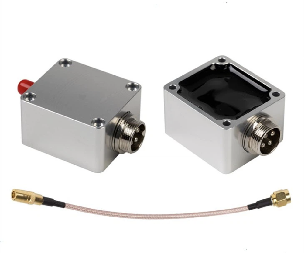
There are a number of capacitive sensors with this same basic form factor. This post covers the “BCL-AMP Amplifier Preamplifier Sensor For Friendess BCS100 Height Controller FSCUT1000 FSCUT2000 System” amp. As of the time this article was written, this amps is available for $56 US at www.aliexpress.us/item/3256804585924423.html.
Electrical interface to the amp
The functionality of the GX16 4-pin circular aviation connector on the amp seems to be one of the great mysteries of the Internet. As far as we have been able to find, no data sheet or manual for the amp exists, and the circuit diagrams provided by machine integrators do not provide enough detail to determine how to interface with the amp. As a result, we’ve had to reverse engineer the device to determine how to properly interface with it. The results of that experimentation have led us to the following pin functions, with the pins numbered per the GX16 connector spec:PinFunctionNotes1+5V DC5V DC supplied to the amp2Signal outA ~5V variable frequency pulse train output3GND0V DC supplied to the amp.4SHIELDThis is the one pin that you can find conclusively documented on the Internet. This pin should be tied to the cable shield. Internal to the amp, pins 3 and 4 are tied together to the ground plane, with pin 3 going through an RF choke inside the device.
With this hookup and some capacitive input on the small coax connector you can observe a variable-frequency output on pin 2 of the amp.
Isolating and cleaning up the amp output
The variable frequency output of the amp is unfortunately not a very clean signal. To clean up this signal we used a SN74HC14N schmitt trigger:

which creates a much cleaner square wave. VCC is wired to +5V and per the data sheet all of the inputs except for one are tied to ground so they don’t float. The output of pin 2 on the amp is wired to one of the trigger inputs, and the output of the trigger is wired to our Mesa 5i25 hostmot2 encoder A-phase input. The SN74HC14N also provides a modest level of signal isolation.
Capacitive frequency response
The following values were measured in a bench setup using a variable capacitor:CapacitanceFrequency85nF2.50MHz123nF2.00MHz166pF1.67MHz210pF1.54MHz233pF1.44MHz
The response is not linear. The closer the metal is to the laser head (the higher the capacitance), the lower the frequency output is. When there was a short the output frequency drops significantly.
Interfacing to LinuxCNC
Because the amplifier outputs a variable frequency signal, the output of the amp can be treated as an encoder input with the velocity representing the value of the signal. This makes it conceptually similar to a THCAD Mesa device. We are using a Mesa 5i25 board for high speed I/O, and so we can configure a hostmot2 encoder (linuxcnc.org/docs/html/man/man9/hostmot2.9.html#Encoder) via pncconf to read the amp output. Since we are only reading a pulse train and not a quadrature encoder this encoder needs to be in “counter-mode” so that each rising edge of the phase-A input is counted, and the value on phase-B is ignored.
The relatively high frequencies output from the sensor (up to ~3MHz) create some special considerations for interfacing. The Mesa card’s FPGA is fast enough to read the signal, but for the fastest signals of the amps, the “filter” setting of the hostmot2 encoder should be set to “False” since 15 sample clocks at 25MHz is too long to successfully sample a ~3MHz signal. The non-default (filter = false) 3 clocks should be fast enough, and with the schmitt trigger the signal is clean enough to work well with a three clock transition.
(bit r/w) filter
If set to True (the default), the quadrature counter needs 15 sample clocks to register a change on any of the three input lines (any pulse shorter than this is rejected as noise). If set to False, the quadrature counter needs only 3 clocks to register a change. The default encoder sample clock runs at approximately 25 to 33 MHz but can be changed globally with the sample-frequency or muxed-sample-frequency pin.
Your hal file will need something like the following:
setp    hm2_5i25.0.encoder.00.counter-mode 1
setp    hm2_5i25.0.encoder.00.filter 0
With this configuration in place, you can use Halscope or Halmeter to see the “velocity” response of the encoder change with the distance to the metal. The effective response range is around 0.1 inches.
As of LinuxCNC 2.9.2, pncconf does not enable setting the filter of the encoder, so I’ve created a shell script with the Linux sed tool to fix the generated configuration:
sed -i -e 's/^setp hm2_5i25.0.encoder.00.filter 1/setp hm2_5i25.0.encoder.00.filter 0/' ~/linuxcnc/configs/laser_cutter/laser_cutter.halThe output of the encoder velocity from a 0.1” Z move can be seen below:
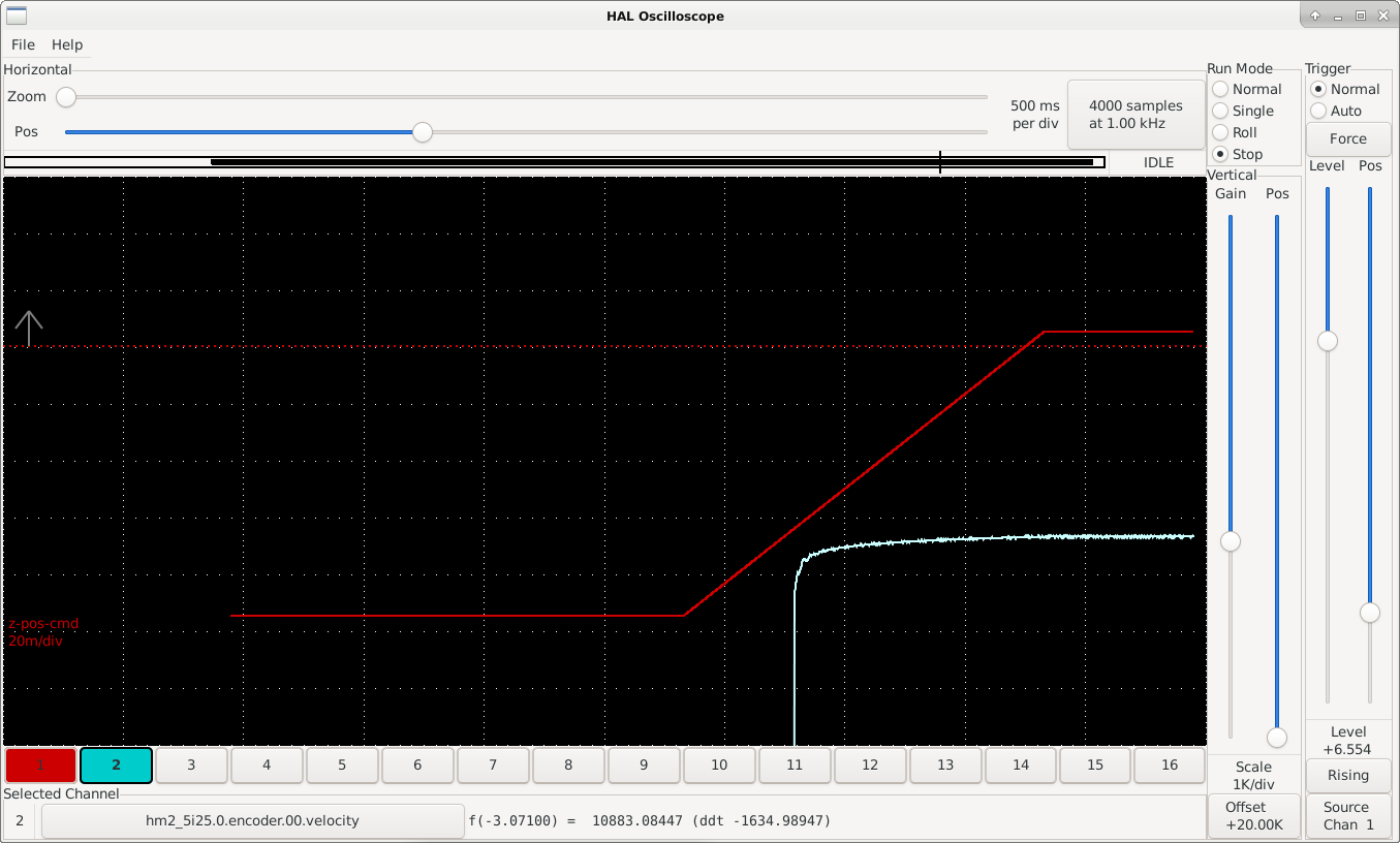
Our next steps are to set up plasmaC and use the capacitive sensor encoder's "velocity" value to hold height over the work piece.
Attachments:
Please Log in or Create an account to join the conversation.
- shasse
- Offline
- Premium Member
-
- Posts: 97
- Thank you received: 58
Pin 1: + 5VDC, 5V DC supplied to the amp
Pin 2: Signal out, A ~5V variable frequency pulse train output
Pin 3: GND, 0V DC supplied to the amp
Pin 4: SHIELD, This is the one pin that you can find conclusively documented on the Internet. This pin should be tied to the cable shield. Internal to the amp, pins 3 and 4 are tied together to the ground plane, with pin 3 going through an RF choke inside the device.
The frequency response of the capacitive sensor:
85nF:  2.50MHz
123nF: 2.00MHz
166pF: 1.67MHz
210pF: 1.54MHz
233pF: 1.44MHzPlease Log in or Create an account to join the conversation.
- tommylight
-

- Away
- Moderator
-

- Posts: 21709
- Thank you received: 7417
Please Log in or Create an account to join the conversation.
- Uthayne
- Offline
- Premium Member
-
- Posts: 147
- Thank you received: 49
I've wired up my BCL-AMP as you've described, +5v on pin 1, Signal Out on pin 2, GND on pin 3. For pin 4, I've let that just be unconnected for now; should this connect to something? I was thinking since it's already connected in the BCL-AMP that I wouldn't want to connect the connector end to ground as well as that could create a ground loop.
My signal (pin 2) goes into pin 1A (input) of a TC74HC14APF Schmitt Trigger similar to yours. I've tied all other inputs on the trigger to GND per the datasheet and supplied +5V from the mesa 7i76e encoder header. The output (1Y) of the trigger goes to the encoder A input, with the card set in TTL mode. My HAL is set up with counter-mode = 1 and filter = 0.
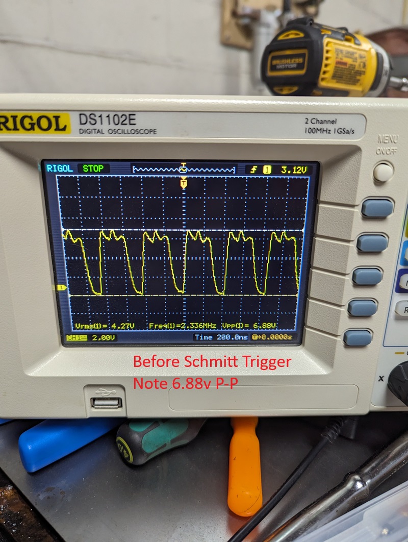
With an oscilloscope probe on the output pin of the schmitt trigger and gnd connected, I can view the frequency response of the sensor. Mine has a no-sense value of about 2.33 MHz. It responds by decreasing frequency when I touch it, or move a metallic object nearby. The schmitt trigger does clean up the signal, but I still wouldn't call it a clean square wave. One thing to note is that I did disconnect the BCL-AMP and put some capacitors inside the connector to do my own bench testing. The output signal on the scope is very stable (frequency wise) with a constant capacitance.
I'm having issues in linuxcnc getting a stable reading from the encoder velocity's signal. Viewing the velocity signal with the scope, there is 0 value when it is idle (nothing nearby) and it bounces all around whenever I touch it. I also basically have to be touching it to get a response on the velocity signal. I would say it's not even as sensitive as yours (~0.100"). If I sit a piece of metal within the detection range, the velocity value is 0 unless its touching. I'm sure it's noise driven, just can't seem to find it.
What does your velocity signal read when the sensor is idle and not near anything?

Attachments:
Please Log in or Create an account to join the conversation.
- shasse
- Offline
- Premium Member
-
- Posts: 97
- Thank you received: 58
counter-mode 1
filter 0
for your encoder, I'd check via halmeter to see if your encoder counts are constantly going up at idle. They should be in my experience. I'd also double check via halmeter or "halcmd show all" at a command prompt that the counter-mode and filter are getting set the way you think they are for your encoder.
One difference between your setup and mine is that I wired the encoder straight to the Mesa Anything IO board (originally a 5i25 then a 7I92TF). Even then I had to set the "filter 0" to get the performance fast enough. From the manual, the 7i76e encoder looks plenty fast (a count rate of 10MHz). So that seems fine.
If you want to run "halcmd show all" a couple of times waiting at least a few seconds between executions it'd be interesting to see what the encoder is doing. Something like:
halcmd show all > run-1.txt
halcmd show all > run-2.txt
and then share the run-1.txt and run-2.txt files here.
Thanks, and glad to have someone else getting a fiber laser going with LinuxCNC! We've started to tune ours in and cut real parts. What laser source are you planning to use?
Scott
Please Log in or Create an account to join the conversation.
- PCW
-

- Away
- Moderator
-
- Posts: 17971
- Thank you received: 5270
If that is still not fast enough, you can
increase the encoder sampling rate.
Note that the pulse width is less than 200 ns.
which means you would likely have to increase
the sampling rate from the default
Please Log in or Create an account to join the conversation.
- Uthayne
- Offline
- Premium Member
-
- Posts: 147
- Thank you received: 49
At idle, counts remains unchanged unless I physically touch the nozzle, and then it will increase. I’ll have to check halcmd outputs tomorrow and I’ll post.
Yeah, I’ve wondered about the counter rate. I have a 7i76e with a 7i85s. This was originally plugged into the 7i85s but I read in the manual the encoders are muxed to save pins which limits count rate to 2-3 MHz. I’ve since plugged it into the 7i76e encoder spot.
Great to hear you having success. Are you finding any limitations with the low sensor range with things such as tip ups? A lot of the Chinese systems I’ve seen can track 6mm and more sense distance. Perhaps it’s not using this amplifier.
I have a Raycus 1000w with a Raytools BM110 auto focus head.
@PCW encoder filter is set to 0. Will try increasing sample rate and report back.
Please Log in or Create an account to join the conversation.
- Uthayne
- Offline
- Premium Member
-
- Posts: 147
- Thank you received: 49
I first tried updating the sample frequency:
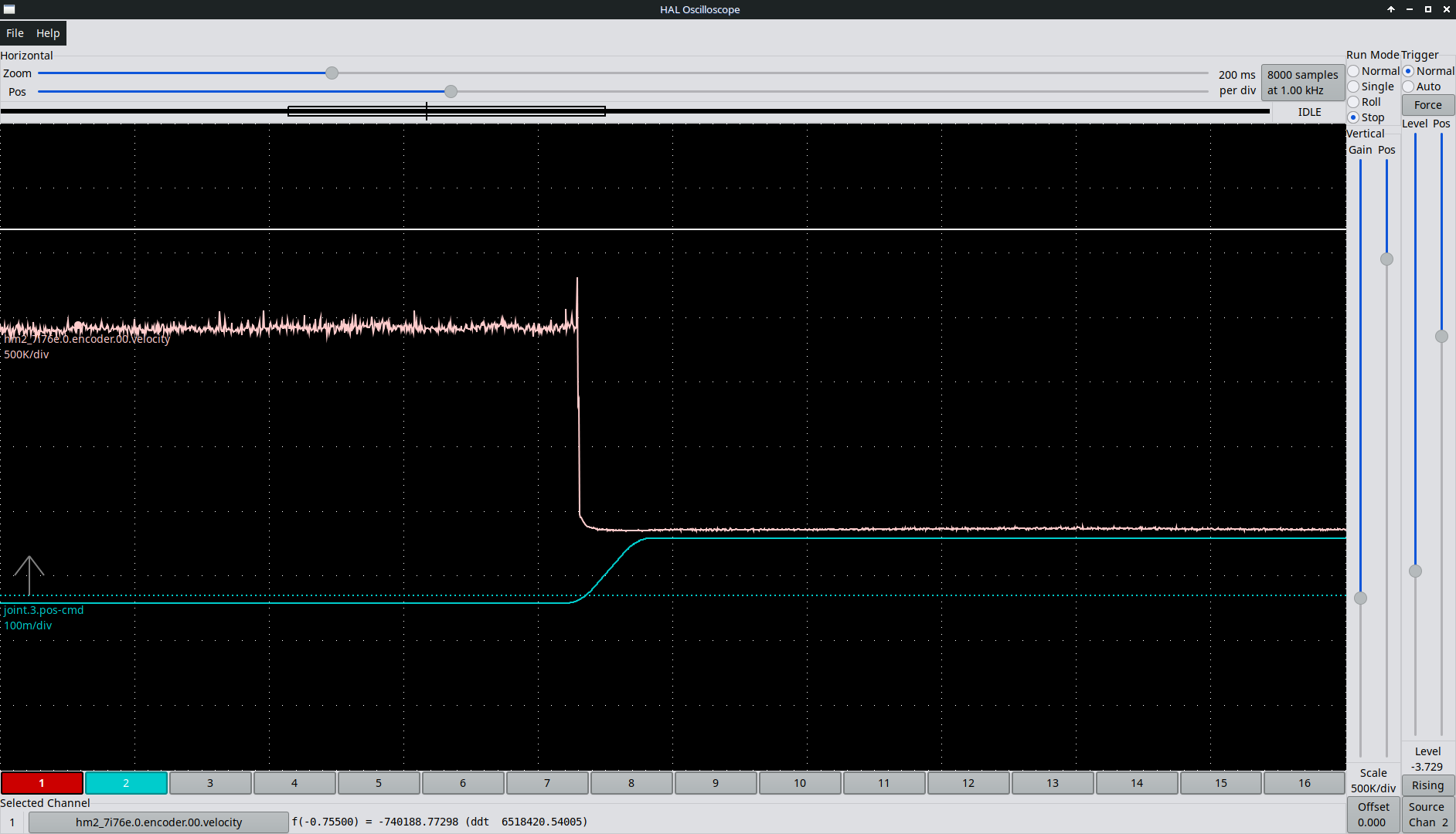
setp hm2_7i76e.0.encoder.muxed-sample-frequency 25000000It was at 8333333 previously (8.333 MHz?), but this higher sample rate didn't solve the issue. I went back and flashed my 7i76e with the stock firmware, changing the 7i76e encoder back to a quad encoder instead of muxed. With all other things remaining the same as before, my signal is now being read, and looks very close to yours. Although the value is inverted, I can just scale it negatively.
Would you mind sharing your hal/ini files? I'm interested in how you scaled it to a reasonable value while maintaining resolution. It is a very small window based on the cut height required to keep it on target.
Here's some data, 0.100" Z move. capacitance.txt is csv scope output data
PCW: Can the 7i76e+7i85s firmware be changed to just "A" input encoders and bypass the need to have muxed encoders that are sample limited? Would this work? My setup requires 3 different single ended encoder "A" inputs, 7 stepgens, and 2 pwmgens.
Please Log in or Create an account to join the conversation.
- PCW
-
- Away
- Moderator
-
- Posts: 17971
- Thank you received: 5270
normal encoders but not both. In order to get along with
the 7I85S you would need to stay with muxed encoders.
Another option would be to use a different module to read
frequency. The Period module can measure frequency as well as
period but does require using LinuxCNC master (2.10)
A hardware fix would be to use a flip-flop (74HC74 say)
to get a ~1 MHz or 500 KHz square wave rather than
the narrow (120 ns?) pulse that's hard to capture.
Please Log in or Create an account to join the conversation.
- Uthayne
- Offline
- Premium Member
-
- Posts: 147
- Thank you received: 49
I am open to using the Period module as I am on 2.10. I could not find a section on it in the documentation. Do you have anything to point me to how to use it?
A hardware solution would be nice as well, thanks!
Please Log in or Create an account to join the conversation.