ProbeBasic and sidemount, retractable 3D Probe
- IB_CnC
- Offline
- Senior Member
-

Less
More
- Posts: 42
- Thank you received: 14
17 Jan 2025 19:51 - 17 Jan 2025 20:02 #319217
by IB_CnC
ProbeBasic and sidemount, retractable 3D Probe was created by IB_CnC
Hi, I'm new over here. ")
I made a CNC router with a retractable 3D probe mounted next to the ATC Spindle.
I also installed ProbeBasic last year, as it seems to be a fantastic GUI with everything I could want from my CNC router.
So far I have ProbeBasic up and running and I can run the probe subroutines.
But my retractable, offsetted 3D probe configuration is maybe a bit special and needs a bit of customization to work.
I'm hoping its possible in ProbeBasic.
Before I start hacking away, can someone point me in the right direction for the following:
- Configuring the offset position of the 3D probe relative to the spindle
- Programming a command that triggers an output, when initiating a probing subroutine (which I can use to control a pneumatic 3/2 valve). Would I need to add this to every subroutine, or is there an easier way?
- And maybe an interlock to make sure no tool is loaded when probing
Any help is much appreciated.)
I made a CNC router with a retractable 3D probe mounted next to the ATC Spindle.
I also installed ProbeBasic last year, as it seems to be a fantastic GUI with everything I could want from my CNC router.
So far I have ProbeBasic up and running and I can run the probe subroutines.
But my retractable, offsetted 3D probe configuration is maybe a bit special and needs a bit of customization to work.
I'm hoping its possible in ProbeBasic.
Before I start hacking away
, can someone point me in the right direction for the following:- Configuring the offset position of the 3D probe relative to the spindle
- Programming a command that triggers an output, when initiating a probing subroutine (which I can use to control a pneumatic 3/2 valve). Would I need to add this to every subroutine, or is there an easier way?
- And maybe an interlock to make sure no tool is loaded when probing
Any help is much appreciated.
)
Last edit: 17 Jan 2025 20:02 by IB_CnC.
Please Log in or Create an account to join the conversation.
- Lcvette
-

- Offline
- Moderator
-

Less
More
- Posts: 1630
- Thank you received: 760
17 Jan 2025 22:49 #319228
by Lcvette
Replied by Lcvette on topic ProbeBasic and sidemount, retractable 3D Probe
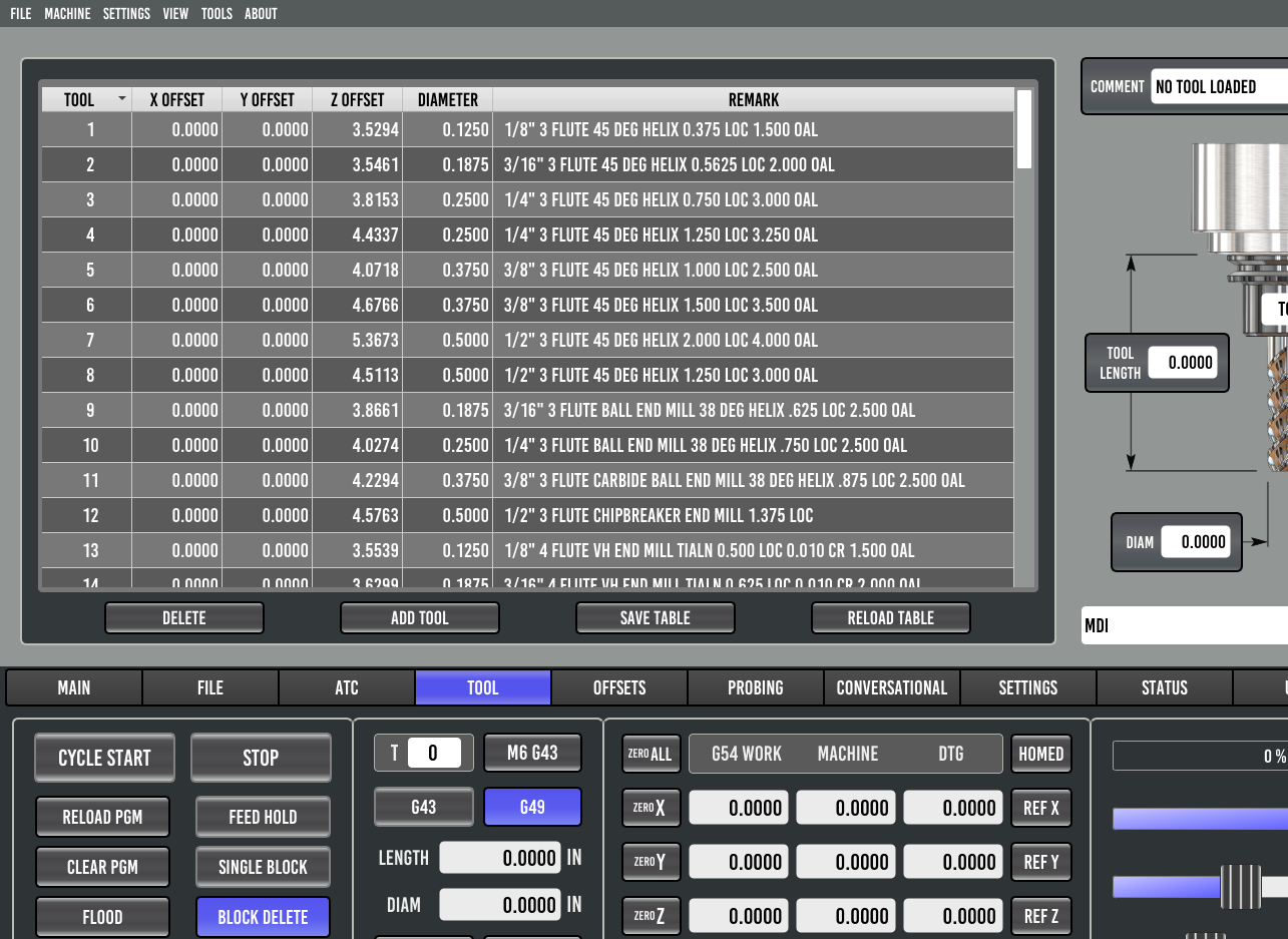
very easy, enter an x and y offset in the tool table for the probe. these are normally 0.0000 since the tool and spindle share the same centerline, but if your probe is offset, you can find the center of a probe calibration ring with an indicator on the spindle, and set a work offset to zero for x and y. then use the probe (with the probe tool offset for x and y set to zero and use the probe position only option on the probing page. when the center has been probed, the x and y dro's will show you how far from the spindle centerline the offset probe center is. enter these in the tool table under the x and y offset column, save and reload the table. if the entries are correct, the main dro's should now show zero.
now when you load the probe tool, the tool offset is called up which will include the x and y offset. so when you probe the work to set an offset it will be taken into account and when the probe tool is unloaded in the user interface and its offset deactivated the zero point will correspond to the spindle centerline.
if you do not have the x and y columns showing in the tool table, open the custom_config.yml file from your config folder and at XY to the tool table display settings as shown below:
This will now display those columns in the tool table when you next run probe basic!
Enjoy!
Chris
now when you load the probe tool, the tool offset is called up which will include the x and y offset. so when you probe the work to set an offset it will be taken into account and when the probe tool is unloaded in the user interface and its offset deactivated the zero point will correspond to the spindle centerline.
if you do not have the x and y columns showing in the tool table, open the custom_config.yml file from your config folder and at XY to the tool table display settings as shown below:
# example of a machine specific settings
windows:
  mainwindow:
    kwargs:
      confirm_exit: false

data_plugins:
  tooltable:
    provider: qtpyvcp.plugins.tool_table:ToolTable
    kwargs:
      columns: TXYZDR
This will now display those columns in the tool table when you next run probe basic!
Enjoy!
Chris
The following user(s) said Thank You: Unlogic
Please Log in or Create an account to join the conversation.
- Lcvette
-
- Offline
- Moderator
-
Less
More
- Posts: 1630
- Thank you received: 760
17 Jan 2025 22:54 #319229
by Lcvette
Replied by Lcvette on topic ProbeBasic and sidemount, retractable 3D Probe
The tool table should look like this once you add X and Y to the custom_config.yml file:
Attachments:
Please Log in or Create an account to join the conversation.
- IB_CnC
- Offline
- Senior Member
-
Less
More
- Posts: 42
- Thank you received: 14
18 Jan 2025 10:59 - 18 Jan 2025 11:06 #319267
by IB_CnC
Replied by IB_CnC on topic ProbeBasic and sidemount, retractable 3D Probe
Great, got it to work, thanks a lot!
You are the creator of Probe Basic right?
I must say it's really impressive this user interface which you have created, on par or better than many OEM software I have seen.
I haven't made a tool changer carousel yet, but plan to make one with geneva wheel.
When I combine the side-probe with the carousel, if I understand correctly the sequence would be:
- Unload the currently mounted tool in the ATC-carousel tab
- Load the Probe via the Tool tab (only in gui)
- Probe the stock
- Unload probe in Tool tab
- Load tool with ATC-carousel tab or start program.
Last edit: 18 Jan 2025 11:06 by IB_CnC.
Please Log in or Create an account to join the conversation.
- Lcvette
-
- Offline
- Moderator
-
Less
More
- Posts: 1630
- Thank you received: 760
18 Jan 2025 14:37 #319281
by Lcvette
Replied by Lcvette on topic ProbeBasic and sidemount, retractable 3D Probe
For now yes that is correct. we have a branch we are working on with a database type tool table which will allow for many more functional options and usable tool parameters to be stored and called upon during subroutines. one of those parameters will be tool storage so it knows which tools are storable in the atc and which are not etc. there will be some really awesome updates coming with the tool database updates.
The following user(s) said Thank You: Unlogic, IB_CnC
Please Log in or Create an account to join the conversation.
- IB_CnC
- Offline
- Senior Member
-
Less
More
- Posts: 42
- Thank you received: 14
09 Feb 2025 13:48 - 09 Feb 2025 13:51 #321063
by IB_CnC
Replied by IB_CnC on topic ProbeBasic and sidemount, retractable 3D Probe
Got it to work with auto extending the probe.
I've programmed the probe to automatically extend when the machine is in probing motion state.
The motion state 5 (probing) is setting a flipflip signal, which is bound to the output pin for a relay and pneumatic valve.
The flipflop bit resets when the machine program is in idle state (which for some reason seems to be inverted "program-running").
Altough I probably add a manual switch or button later, as this way you can't really accurately place the probe before starting the subroutine.
And it also extends when doing a tool offset measurement.
Here I was probing a set square:
Last edit: 09 Feb 2025 13:51 by IB_CnC.
Please Log in or Create an account to join the conversation.
- IB_CnC
- Offline
- Senior Member
-
Less
More
- Posts: 42
- Thank you received: 14
09 Feb 2025 13:59 - 09 Feb 2025 14:00 #321064
by IB_CnC
Replied by IB_CnC on topic ProbeBasic and sidemount, retractable 3D Probe
I'm building the carousel at the moment, it's a ride along design with a geneva drive wheel.
Also with a retractable dust sucker, so should be fun to get this all to work.

Also with a retractable dust sucker, so should be fun to get this all to work.
Last edit: 09 Feb 2025 14:00 by IB_CnC.
Please Log in or Create an account to join the conversation.
- Lcvette
-
- Offline
- Moderator
-
Less
More
- Posts: 1630
- Thank you received: 760
09 Feb 2025 18:00 #321075
by Lcvette
Replied by Lcvette on topic ProbeBasic and sidemount, retractable 3D Probe
nice.. have you considered simply adding the probing tool number parameter to the toolchange call with an if statement? this way anytime you load or unload the probe tool it would activate a subroutine to either deploy the probe or retract it?
interesting concept on the ride along design. that is going to add quite a bit of unbalanced weight to the machine maybe? have you considered how that will affect high speed motion and inertia differences for the slaved drive motors?
I am about to release a fully integrated RACK type atc integration for probe basic, this could be a simpler and more economical method for atc maybe?
Please Log in or Create an account to join the conversation.
- IB_CnC
- Offline
- Senior Member
-
Less
More
- Posts: 42
- Thank you received: 14
09 Feb 2025 18:29 - 09 Feb 2025 18:38 #321086
by IB_CnC
Replied by IB_CnC on topic ProbeBasic and sidemount, retractable 3D Probe
Lcvette nice.. have you considered simply adding the probing tool number parameter to the toolchange call with an if statement? this way anytime you load or unload the probe tool it would activate a subroutine to either deploy the probe or retract it?
Great idea, that should work perfectly..... thanks!
Lcvette Interesting concept on the ride along design. that is going to add quite a bit of unbalanced weight to the machine maybe? have you considered how that will affect high speed motion and inertia differences for the slaved drive motors?
Yes, I did consider the difference in inertia, altough I didn't go into calculations for this.
The motor on the side of the toolchanger will have to work harder on accel and decel. For accuracy or chatter I don't think it will do much, as it's directly mounted on the beam which is also connected to lineair rail and 20mm ballscrew ( ballscrew on each side).
With routers, the Z assembly could anyway be all the way on the side and is even heavier. It does add up ofcourse...
The weight is not too bad, the plate diameter of the carousel is 200mm and I use ISO20, so quite compact.
I could make the construction lighter by milling some pockets if needed.
Typically I jog the machine at 12000mm/min and 1000 accel/decel, but am machining at half of that at a maximum so there's some room too dial it down still should the need arrive.
Lcvette I am about to release a fully integrated RACK type atc integration for probe basic, this could be a simpler and more economical method for atc maybe?
The problem is the rack type will make me lose work area, and I need the full Y axis range.
I build the router to cut moulds for composites (hydrofoils) and boards, and when I started building the router I thought 1000 x 1640mm would be fine. But the boards are longer now and my work area is already 10-20cm too short.
Last edit: 09 Feb 2025 18:38 by IB_CnC.
Please Log in or Create an account to join the conversation.
- Lcvette
-
- Offline
- Moderator
-
Less
More
- Posts: 1630
- Thank you received: 760
09 Feb 2025 19:12 #321097
by Lcvette
Replied by Lcvette on topic ProbeBasic and sidemount, retractable 3D Probe
is there enough cushion on the opposite side of the X extrusion to slide everything over enough to have a tool rack on the outside of the left side gantry upright? or maybe consider the cost comparison/complexity to be able to add a longer set of rails and a bolt on extension to make that possible?
Please Log in or Create an account to join the conversation.
Moderators: KCJ, Lcvette
Time to create page: 0.220 seconds