- User Interfaces
- Other User Interfaces
- QtPyVCP
- Probe Basic — 4-axis XYZB wrapped rotary backplot support
Probe Basic — 4-axis XYZB wrapped rotary backplot support
- dredivan
- Away
- New Member
-

Less
More
- Posts: 14
- Thank you received: 1
15 Apr 2026 10:44 #345574
by dredivan
Probe Basic — 4-axis XYZB wrapped rotary backplot support was created by dredivan
Hi,
Setting up Probe Basic 0.6.6 on a 4-axis gantry machine (MPCNC with a fixed rotary B axis mounted at the end of the Y travel).
Configuration:
- LinuxCNC 2.9.8
- Mesa 7I76E (Ethernet)
- trivkins coordinates=XXYYZB, 6 joints
- B axis is a rotary chuck, fixed position at Y=700mm
What works:
DRO displays all 4 axes correctly using DRO_DISPLAY = XYZAB (A axis is unused but present — there is no XYZB option available).
What does not work:
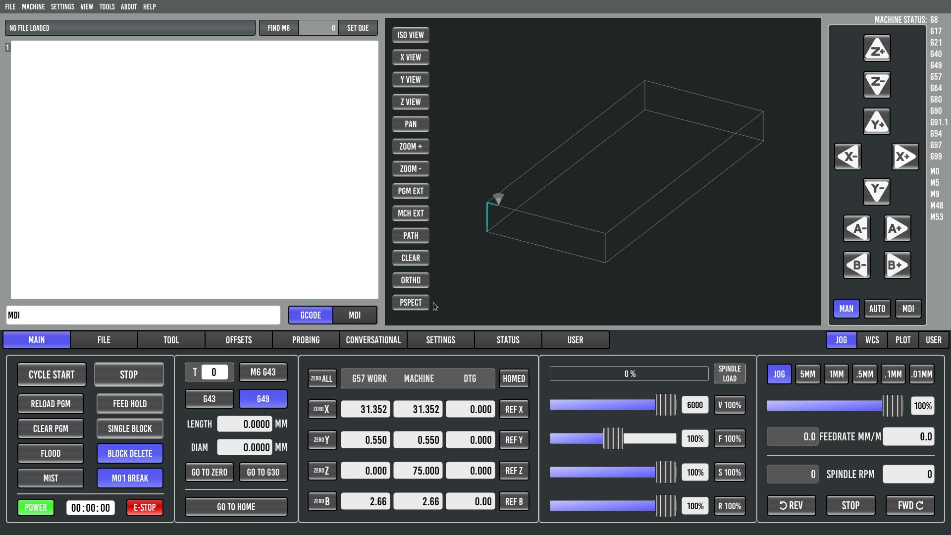
The backplot renders the toolpath as 3-axis only — B axis rotation is not applied when building the path. For wrapped rotary applications (tube machining) the toolpath preview is not meaningful.
Also, machine bounds are not displayed in the 4-axis config, while they display correctly in the 3-axis config on the same machine.
Are there any plans to support wrapped rotary backplot rendering in Probe Basic / qtpyvcp?
3 axis configuration - mpcnc_probebasic.ini
4 axis configuration - probebasic_4b.ini
Setting up Probe Basic 0.6.6 on a 4-axis gantry machine (MPCNC with a fixed rotary B axis mounted at the end of the Y travel).
Configuration:
- LinuxCNC 2.9.8
- Mesa 7I76E (Ethernet)
- trivkins coordinates=XXYYZB, 6 joints
- B axis is a rotary chuck, fixed position at Y=700mm
What works:
DRO displays all 4 axes correctly using DRO_DISPLAY = XYZAB (A axis is unused but present — there is no XYZB option available).
What does not work:
The backplot renders the toolpath as 3-axis only — B axis rotation is not applied when building the path. For wrapped rotary applications (tube machining) the toolpath preview is not meaningful.
Also, machine bounds are not displayed in the 4-axis config, while they display correctly in the 3-axis config on the same machine.
Are there any plans to support wrapped rotary backplot rendering in Probe Basic / qtpyvcp?
3 axis configuration - mpcnc_probebasic.ini
4 axis configuration - probebasic_4b.ini
Please Log in or Create an account to join the conversation.
- Lcvette
-

- Offline
- Moderator
-

Less
More
- Posts: 1634
- Thank you received: 763
15 Apr 2026 20:07 #345579
by Lcvette
Replied by Lcvette on topic Probe Basic — 4-axis XYZB wrapped rotary backplot support
do you have the plot turned on for machine bounds in the ui? sidebar tab "PLOT"
for the dro display, you can use the user custom dro template and setup however you desire, just remove the rows for a and c and leave xyzb
for the wrapped rotary, this will be something coming down the line, we are currently working on multi axis plotting and simulation so if you have a model of your machine and would like to be a tester for the currently existing test branch you can give it a try if you like, the feedback would be good for us to have someone outputting multiaxis gcode for testing.
Please Log in or Create an account to join the conversation.
- dredivan
- Away
- New Member
-
Less
More
- Posts: 14
- Thank you received: 1
16 Apr 2026 04:51 #345585
by dredivan
Replied by dredivan on topic Probe Basic — 4-axis XYZB wrapped rotary backplot support
Regarding DRO — I already did exactly that, edited dros_user.ui removing the A and C rows. DRO now shows only XYZB. However the A+/A- jog buttons remain — they are controlled separately from the DRO file. Is there a way to remove the unused jog buttons without touching system files?
Regarding wrapped rotary — very interesting! I am ready to test. What do I need to get started with the test branch and what machine model is required?
Regarding wrapped rotary — very interesting! I am ready to test. What do I need to get started with the test branch and what machine model is required?
Please Log in or Create an account to join the conversation.
- dredivan
- Away
- New Member
-
Less
More
- Posts: 14
- Thank you received: 1
16 Apr 2026 10:19 - 16 Apr 2026 10:22 #345588
by dredivan
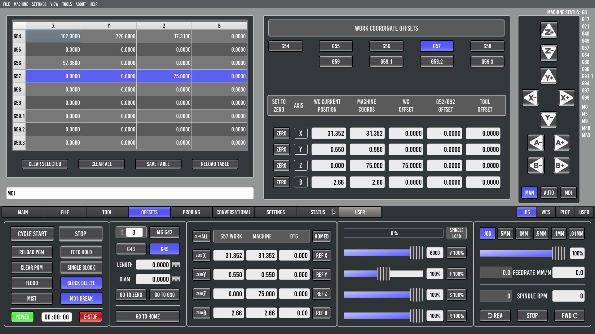
Update: DRO is now showing only XYZB.
Edited dros_user.ui and offset_dros_user.ui removing the A and C rows and fixed the ZERO ALL command.
Added to INI:
DRO_DISPLAY = USER
USER_DROS_PATH = user_dro_display/
OFFSET_COLUMNS = XYZB
Screenshot attached.
The A+/A- jog buttons are still present — is there a way to remove them without touching system files?
Regarding the wrapped rotary test branch — ready to test. My setup is a standard XYZ milling machine with a B axis mounted parallel to Y. Where can I get the test branch and how do I get started?
Replied by dredivan on topic Probe Basic — 4-axis XYZB wrapped rotary backplot support
Update: DRO is now showing only XYZB.
Edited dros_user.ui and offset_dros_user.ui removing the A and C rows and fixed the ZERO ALL command.
Added to INI:
DRO_DISPLAY = USER
USER_DROS_PATH = user_dro_display/
OFFSET_COLUMNS = XYZB
Screenshot attached.
The A+/A- jog buttons are still present — is there a way to remove them without touching system files?
Regarding the wrapped rotary test branch — ready to test. My setup is a standard XYZ milling machine with a B axis mounted parallel to Y. Where can I get the test branch and how do I get started?
Last edit: 16 Apr 2026 10:22 by dredivan.
Please Log in or Create an account to join the conversation.
- davids
- Offline
- New Member
-
Less
More
- Posts: 1
- Thank you received: 0
28 Apr 2026 16:09 #346016
by davids
Replied by davids on topic Probe Basic — 4-axis XYZB wrapped rotary backplot support
Hi Lcvette,
Following up on your offer in this thread to test the multi-axis plotting / simulation branch — I'd like to put my machine forward as a test case. It's a different geometry from dredivan's MPCNC, so flagging that up front in case it's useful (or not) for what you're prototyping.
Machine: — 4-axis cylindrical/polar additive system tower-crane style. Not a wrapped-rotary gantry; the entire arm rotates around a stationary work area.
Configuration:
LinuxCNC 2.9.8 on Raspberry Pi 5 (Bookworm + PREEMPT_RT)
Mesa 7i96S
KINEMATICS = trivkins coordinates=XBZA kinstype=1 (joints 0–3 = X, B, Z, A)
Axes:
A — base rotation, 0–360° continuous, carries the entire Z tower + X arm + B head
Z — vertical linear, 0–2470 mm, rides up the rotating tower
X — radial linear, 952–2760 mm (radial distance from tower center to B housing — not Cartesian X)
B — end-of-arm rotation, ±90°, rotates about a vertical axis at the end of the X arm; B=0 means the 652 mm tool arm is aligned with the X arm (radially outward)
G-code is pre-computed in polar/cylindrical space by the CAM post-processor and emitted as dense waypoints in G93 inverse-time.
Sample line:
G93 G1 X2054.287 Z6 A118.183 B11.055 F423.731
→ B housing at radius 2054.287 mm, height 6 mm, base 118.183° CW, tool arm tilted +11.055° from radial; move duration ≈ 1/423.731 min ≈ 0.14 s.
Stock backplots render this as joint space and produce nonsense, which is why a wrapped/transformed preview would be a big deal for us. If the test branch can accept a custom transform (or already exposes a forward-kinematics hook for the canon), I can supply realistic .ngc files and run them on the actual machine.
let me know how I can be useful. Hope we can find a way for me to be a tester for your multi axis plotter!
— David
Please Log in or Create an account to join the conversation.
- Lcvette
-
- Offline
- Moderator
-
Less
More
- Posts: 1634
- Thank you received: 763
28 Apr 2026 17:29 - 28 Apr 2026 17:34 #346017
by Lcvette
Replied by Lcvette on topic Probe Basic — 4-axis XYZB wrapped rotary backplot support
@
dredivan
I just pushed an update on the develop branch for bookworm version that specifies the jog buttons to display based on the display>geometry= setting in the ini file, if you update and specify your desired axis buttons there for jogging it will be correct now.
I just pushed an update on the develop branch for bookworm version that specifies the jog buttons to display based on the display>geometry= setting in the ini file, if you update and specify your desired axis buttons there for jogging it will be correct now.
Last edit: 28 Apr 2026 17:34 by Lcvette.
Please Log in or Create an account to join the conversation.
- Lcvette
-
- Offline
- Moderator
-
Less
More
- Posts: 1634
- Thank you received: 763
28 Apr 2026 17:33 - 28 Apr 2026 17:35 #346018
by Lcvette
Replied by Lcvette on topic Probe Basic — 4-axis XYZB wrapped rotary backplot support
@
davids
hmm i not even sure where i would start with that, seems pretty unique. I would maybe wait until the latest pyside6 version is released with docs on setting up the machine simulation and try there and report back. I am working on the docs now and then will be uploading the installation requirements for pyside6 for testers, will be a couple days while i try and find time to finish up the doc reconfiguration for bookworm/trixie separation.
hmm i not even sure where i would start with that, seems pretty unique. I would maybe wait until the latest pyside6 version is released with docs on setting up the machine simulation and try there and report back. I am working on the docs now and then will be uploading the installation requirements for pyside6 for testers, will be a couple days while i try and find time to finish up the doc reconfiguration for bookworm/trixie separation.
Last edit: 28 Apr 2026 17:35 by Lcvette.
Please Log in or Create an account to join the conversation.
Moderators: KCJ, Lcvette
- User Interfaces
- Other User Interfaces
- QtPyVCP
- Probe Basic — 4-axis XYZB wrapped rotary backplot support
Time to create page: 1.622 seconds