about my 48" X 48" X 5" Techno/ISEL woodworking router build
- travis036
-
 Topic Author
- Offline
- Elite Member
-

Less
More
- Posts: 283
- Thank you received: 32
23 Dec 2020 16:11 #192981
by travis036
about my 48" X 48" X 5" Techno/ISEL woodworking router build was created by travis036
some may remember me from other parts of the LinuxCNC forum... i am working on converting my Techno/ISEL gantry woodworking CNC router from printer port control, to a Mesa 7i80HD-16. the machine is about 48" X 48" X 5" of working area, and currently has a Perske 5HP 3-phase (via Chinese VFD) spindle. it is stepper drive (i prefer the "music" of steppers...), and i will likely keep it that way, until i find the "music" to be a pain. ") currently, the project has slowed down, with the holiday prep underway, but i expect to be working full-force again asap.
currently, the project has slowed down, with the holiday prep underway, but i expect to be working full-force again asap.
i look forward to sharing pictures in this thread, when i take them, of the whole machine, and how i put it together.
when i first got it, it was just the Techno/ISEL machine itself. the frame, gantry, Perske spindle, and the steel base. it had some servo motors for all 3 axis, but as i could not find any info on them, or their encoders, i opted for steppers, as the motors and drivers were cheaper than servo hardware.
here is an older picture:
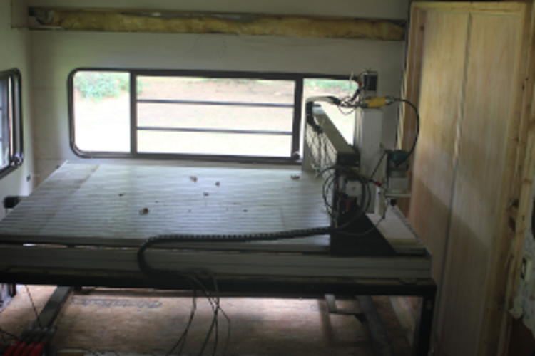
it was taken years ago, before i mounted the Perske spindle back onto it (shown with a Makita RF1101 router attached).
the machine resides in the back of a gutted-out old camper. there are some added double doors added to the camper, to the right, so i can put large material onto the machine without having to get it through the camper door. and if i ever have to move the machine out of the camper, they will work for that too.
the control hardware will be mounted in a small rack enclosure i bought just for this reason, and all will be shielded and isolated using adhesive copper foil designed for electric guitar shielding. the power supplies will all be located at the bottom of the enclosure, away from the EMI sensitive parts. i am on the lookout for a plate of copper or aluminum to mount the stepper drivers on as a heatsink, and it will also be tied in to the shielding, to prevent EMI escaping, or entering. stepper driver signal wire will be CAT-5e STP wire, with the drain wire tied to the shielding (one end only, of course). power wires will be twisted in pairs, feeding each driver, and wrapped with shielding foil. the motor wires don't happen to be twisted-pairs, but they are shielded cables.
the power-supply for the logic, and the 7i80HD-16, a computer power-supply, will be partitioned off from the stepper power-supplies.
the reason for all the careful shielding, is my previous setup had a slight cross-talk issue, so this generation will be over-shielded, as much as i can. and taking tips from Best Wiring Practices , i will try and document and label better, this time...
anyway, been meaning to describe my project for a while now, and more updates and pictures will follow as progress is made.")
~Travis
currently, the project has slowed down, with the holiday prep underway, but i expect to be working full-force again asap.i look forward to sharing pictures in this thread, when i take them, of the whole machine, and how i put it together.
when i first got it, it was just the Techno/ISEL machine itself. the frame, gantry, Perske spindle, and the steel base. it had some servo motors for all 3 axis, but as i could not find any info on them, or their encoders, i opted for steppers, as the motors and drivers were cheaper than servo hardware.
here is an older picture:
it was taken years ago, before i mounted the Perske spindle back onto it (shown with a Makita RF1101 router attached).
the machine resides in the back of a gutted-out old camper. there are some added double doors added to the camper, to the right, so i can put large material onto the machine without having to get it through the camper door. and if i ever have to move the machine out of the camper, they will work for that too.
the control hardware will be mounted in a small rack enclosure i bought just for this reason, and all will be shielded and isolated using adhesive copper foil designed for electric guitar shielding. the power supplies will all be located at the bottom of the enclosure, away from the EMI sensitive parts. i am on the lookout for a plate of copper or aluminum to mount the stepper drivers on as a heatsink, and it will also be tied in to the shielding, to prevent EMI escaping, or entering. stepper driver signal wire will be CAT-5e STP wire, with the drain wire tied to the shielding (one end only, of course). power wires will be twisted in pairs, feeding each driver, and wrapped with shielding foil. the motor wires don't happen to be twisted-pairs, but they are shielded cables.
the power-supply for the logic, and the 7i80HD-16, a computer power-supply, will be partitioned off from the stepper power-supplies.
the reason for all the careful shielding, is my previous setup had a slight cross-talk issue, so this generation will be over-shielded, as much as i can. and taking tips from Best Wiring Practices , i will try and document and label better, this time...
anyway, been meaning to describe my project for a while now, and more updates and pictures will follow as progress is made.
~Travis
Attachments:
The following user(s) said Thank You: tommylight
Please Log in or Create an account to join the conversation.
- tommylight
-

- Away
- Moderator
-

Less
More
- Posts: 21662
- Thank you received: 7400
31 Dec 2020 22:44 #193683
by tommylight
Sound like a nice plan, thank you for sharing.
Happy New Year, all the best.
Tom.
Replied by tommylight on topic about my 48" X 48" X 5" Techno/ISEL woodworking router build
You should see people here when i tell them that the plasma turning on is causing some other equipment in their shop to malfunction, they look at me like i just fell from Jupiter !the reason for all the careful shielding, is my previous setup had a slight cross-talk issue, so this generation will be over-shielded, as much as i can.
Sound like a nice plan, thank you for sharing.
Happy New Year, all the best.
Tom.
The following user(s) said Thank You: travis036
Please Log in or Create an account to join the conversation.
- rodw
-

- Offline
- Platinum Member
-

Less
More
- Posts: 11967
- Thank you received: 4078
01 Jan 2021 10:21 #193712
by rodw
Replied by rodw on topic about my 48" X 48" X 5" Techno/ISEL woodworking router build
From the manual the 7i80HD uses 5 volt I/O. This may not have been a good choice for your machine because such a low voltage is more susceptible to noise because the voltage does not need to change much from noise to affect reliability.
If 24 volt is used, the noise has to alter the voltage much more before it misbehaves, about 10 volts or so. Thats why it is the standard voltage for commercial standards.
I would ask some questions on the Driver boards section where PCW is more likely to see it.. I think Mesa have an adapter for 50 pin cards to 25 pin cards so this may allow you to run a 7i76 and upgrade to 24 volt field power. Alternatively swap your existing card for a 7i76e. If more I/O pins are required, you may need to add another daughtercard to increase the number of pins.
Please Log in or Create an account to join the conversation.
- travis036
-
Topic Author
- Offline
- Elite Member
-
Less
More
- Posts: 283
- Thank you received: 32
01 Jan 2021 10:28 #193713
by travis036
Replied by travis036 on topic about my 48" X 48" X 5" Techno/ISEL woodworking router build
conveniently, i just, as in just now, ordered some 5v to 24v optoisolation boards, as well as some 24v to 5v boards for the inputs. my stepper drivers are 24v compatible with the correct resistors in series, so this all works out.
~Travis
~Travis
The following user(s) said Thank You: rodw
Please Log in or Create an account to join the conversation.
- rodw
-
- Offline
- Platinum Member
-
Less
More
- Posts: 11967
- Thank you received: 4078
01 Jan 2021 11:24 #193716
by rodw
Replied by rodw on topic about my 48" X 48" X 5" Techno/ISEL woodworking router build
Also the LCNC docs on wiring don't mention using a star ground system so that every motor has a seperate ground wire running back to a central ground that in turn is grounded to the electrical system, the cabinet and possibly to a ground rod driven through the slab into the ground. Also ensure that you also run wires from the z axis if necessary. The goal is to ensure there is a path to ground that does not pass through any bearings or linear rails. Hypertherm has a document around this specifically for plasma machines but it would be worth reviewing it.
Also on my machine, I used 5 pin connectors for stepper wiring so the cable shield could pass through into the cabinet and then it was terminated to frame ground right at the stepper controller. Do not connect the shield at the motor end. My latest drivers have a terminal for ground so this worked out well.
Also on my machine, I used 5 pin connectors for stepper wiring so the cable shield could pass through into the cabinet and then it was terminated to frame ground right at the stepper controller. Do not connect the shield at the motor end. My latest drivers have a terminal for ground so this worked out well.
The following user(s) said Thank You: travis036
Please Log in or Create an account to join the conversation.
- travis036
-
Topic Author
- Offline
- Elite Member
-
Less
More
- Posts: 283
- Thank you received: 32
01 Jan 2021 12:04 #193719
by travis036
Replied by travis036 on topic about my 48" X 48" X 5" Techno/ISEL woodworking router build
interesting, i had heard about a star grounding system, but hadn't thought of it. by your description, i am almost already applying it, in that i am centralizing ground, but i still have to apply a ground stake, and some other steps.
i like the mention of grounding the Z-axis, as i had not considered that either. perhaps the gantry may also be grounded, for consistency. i may ground the Z to the gantry, and the gantry to the frame. and the frame to the central grounding. it may be as simple as a ground wire run through each drag-chain, between each axis.
my stepper cable shield drain wire is connected to the metal shield of the connector, and thus to the chassis. not a dedicated pin connection, but it tests positive for conductivity to the chassis. short of changing the connectors, i could add a grounding tail, and fix it with a sheet-metal screw to the chassis.
something occurred to me, just now. the enclosure for my control box is a "some assembly required" type, with each panel painted at the MFG. perhaps i should not consider this as a grounding location... so the stepper cable shields should continue to a proper ground location. either that, or i need to ground each panel of the enclosure (more of a PITA). i planed on sectionalized shielding inside the enclosure anyway, so the only thing that changes really, is what i can and cannot consider a ground.
with a star-ground connection, i will also have to consider what ties to it. AC and DC grounds generally should be independent. i usually consider shielding to be an AC ground, and the DC logic/control power supplies have their own common ground plane. but the stepper driver PSUs... does the DC ground tie to AC ground, Logic DC ground, or float as it's own ground?
~Travis
Please Log in or Create an account to join the conversation.
- travis036
-
Topic Author
- Offline
- Elite Member
-
Less
More
- Posts: 283
- Thank you received: 32
16 Jan 2021 12:56 #195528
by travis036
Replied by travis036 on topic about my 48" X 48" X 5" Techno/ISEL woodworking router build
progress has been slow, due to... lack of ambition, maybe.
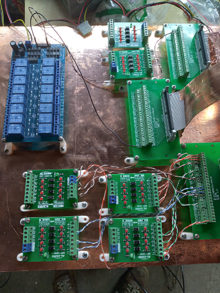
I have so far selected a mounting board (3/4" birch plywood), and covered the surface in copper foil tape for shielding. i then mounted the Mesa card to it using some L PCB mounting feet. i did the same for the 50-pin breakout boards, and the 5v <--> 24v optoisolation modules (each is 4 channel). the ribbon cables from the Mesa card to the breakout boards have been wrapped with copper foil tape, and grounded to the mounting board shielding. the mounting board, when complete, will have a perimeter of wood wrapped in copper foil tape, and a cover that is also shielded. the idea being that all of the control logic will be shielded, and the wires coming in and out will also be shielded (shield drain tied to the mounting board copper).
next to do, is to connect jumper wires from the breakout boards to the optoisolation modules. these are short runs (3" to 6"), so i may be fine with unshielded twisted-pair wires, only because shielding them will be a PITA. i may shield them in the future, if needed.
the stepper drivers will not be mounted on the control mounting board, simply because the mounting board i selected didn't have as much room as i thought it did. they will be mounted to the base of the enclosure, with shielded cable (CAT5e STP) feeding the logic. the power wires feeding the stepper drivers will be made to be twisted-pair.
now, i have changed my mind on the source of power for the system. previously, the power was a few switch-mode power supplies (120Vac input), as well as a ATX computer power supply (supplying 5Vdc, and 12Vdc), and a 24Vdc wall-wort. what i will be changing to, is rather than relying on 120Vac grid power, i will use a couple 12V lead-acid (or AGM) batteries, kept up with an automatic 120Vac charger, and solar power. this way, the power is stable during a power failure, giving me time to either save and shutdown the machine, or with enough battery storage, keep running. the LCNC computer will have a UPS as well, and eventually a standby generator. so with this in mind, i will use a series of step-up and step-down DC-to-DC converters to get the 5V, 12V, 24V, 36V power buses. the only thing that will not get power, will be the spindle, so likely i won't keep running, but will save and pause, and enable a resume button when the power is restored via either grid power, or from the standby generator. so i will need to wire a relay to the grid power, and connect it to activate the E-Stop on power failure.
as for shielding the control enclosure, my choices are to either cover the inside in copper foil tape, or use sheet metal screws to bond the painted panels together. the screws may be easier, but i think the copper foil may be more reliable. i will have to think on that portion.
i also have plans for this spring/summer to move my machine from the old gutted out camper, to a to-be-built shed. working inside the old camper has a lot of disadvantages, mainly lack of room around the machine. with the larger shed, i can also feed it with a sub-panel, and 6AWG wire from the main power panel, as opposed to the 10AWG wire feeding the camper. this will enable more available power for a larger dust-collection system, rather than the shop-vacuum i have currently.
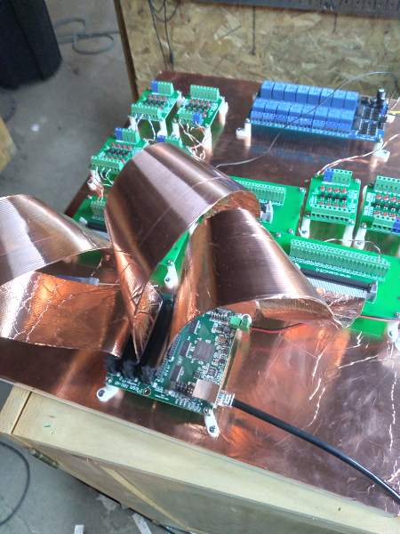
i hope to have the control mounting board more complete by tomorrow, and i will try to remember to take a few pictures. the shiny copper foil definitely adds to the appearance.
~Travis
I have so far selected a mounting board (3/4" birch plywood), and covered the surface in copper foil tape for shielding. i then mounted the Mesa card to it using some L PCB mounting feet. i did the same for the 50-pin breakout boards, and the 5v <--> 24v optoisolation modules (each is 4 channel). the ribbon cables from the Mesa card to the breakout boards have been wrapped with copper foil tape, and grounded to the mounting board shielding. the mounting board, when complete, will have a perimeter of wood wrapped in copper foil tape, and a cover that is also shielded. the idea being that all of the control logic will be shielded, and the wires coming in and out will also be shielded (shield drain tied to the mounting board copper).
next to do, is to connect jumper wires from the breakout boards to the optoisolation modules. these are short runs (3" to 6"), so i may be fine with unshielded twisted-pair wires, only because shielding them will be a PITA. i may shield them in the future, if needed.
the stepper drivers will not be mounted on the control mounting board, simply because the mounting board i selected didn't have as much room as i thought it did. they will be mounted to the base of the enclosure, with shielded cable (CAT5e STP) feeding the logic. the power wires feeding the stepper drivers will be made to be twisted-pair.
now, i have changed my mind on the source of power for the system. previously, the power was a few switch-mode power supplies (120Vac input), as well as a ATX computer power supply (supplying 5Vdc, and 12Vdc), and a 24Vdc wall-wort. what i will be changing to, is rather than relying on 120Vac grid power, i will use a couple 12V lead-acid (or AGM) batteries, kept up with an automatic 120Vac charger, and solar power. this way, the power is stable during a power failure, giving me time to either save and shutdown the machine, or with enough battery storage, keep running. the LCNC computer will have a UPS as well, and eventually a standby generator. so with this in mind, i will use a series of step-up and step-down DC-to-DC converters to get the 5V, 12V, 24V, 36V power buses. the only thing that will not get power, will be the spindle, so likely i won't keep running, but will save and pause, and enable a resume button when the power is restored via either grid power, or from the standby generator. so i will need to wire a relay to the grid power, and connect it to activate the E-Stop on power failure.
as for shielding the control enclosure, my choices are to either cover the inside in copper foil tape, or use sheet metal screws to bond the painted panels together. the screws may be easier, but i think the copper foil may be more reliable. i will have to think on that portion.
i also have plans for this spring/summer to move my machine from the old gutted out camper, to a to-be-built shed. working inside the old camper has a lot of disadvantages, mainly lack of room around the machine. with the larger shed, i can also feed it with a sub-panel, and 6AWG wire from the main power panel, as opposed to the 10AWG wire feeding the camper. this will enable more available power for a larger dust-collection system, rather than the shop-vacuum i have currently.
i hope to have the control mounting board more complete by tomorrow, and i will try to remember to take a few pictures. the shiny copper foil definitely adds to the appearance.
~Travis
Please Log in or Create an account to join the conversation.
- travis036
-
Topic Author
- Offline
- Elite Member
-
Less
More
- Posts: 283
- Thank you received: 32
30 Jan 2021 20:50 #197176
by travis036
Replied by travis036 on topic about my 48" X 48" X 5" Techno/ISEL woodworking router build
Not a huge amount of progress, due to lack of ambition, but i am almost done the control board wiring. i have not added the shielding walls to the backer board yet, nor have i made the shielded cover. i was going good with shielding the wires, but on the many short wires between the Mesa board's breakout boards, and the 5v to 24v opto modules, i resolved myself to just twisted pairs. the relay board really should be shielded from the rest of the controls. perhaps i will just add a shielded partition to isolate it.
thought i would add a couple pics of my slow progress.
~Travis
thought i would add a couple pics of my slow progress.
~Travis
Attachments:
The following user(s) said Thank You: tommylight
Please Log in or Create an account to join the conversation.
- travis036
-
Topic Author
- Offline
- Elite Member
-
Less
More
- Posts: 283
- Thank you received: 32
14 Feb 2021 20:42 #198839
by travis036
Replied by travis036 on topic about my 48" X 48" X 5" Techno/ISEL woodworking router build
made some progress today. i installed the control board into the cabinet, and made some test power hookups with both the 7i80HD-16 and the LCNC computer connected to the remote LAN out in the shed. they talk, and work with the signals correctly! well, i did have to invert some outputs, but when i did, all was well in the kingdom.
my next stage will be to connect the stepper drivers, and the homing signals, and see if i can make some first moves (for the 7i80HD-16).
this may not seem like huge progress, but with all i have going, it is moving along well.
i also still have to make the shielded surrounds and cover for the control board, but when my wiring is completely done, then i will know better where to make the openings for wires.
i have not connected the machine to the control board yet, as i wanted to make sure i would be sending it the correct signals, before i hooked it up and broke something. when i had things up and running, i used my digital oscilloscope to visually verify some signals from the stepgen signals.
as i was unhappy with the number of switching power-supplies cluttering up the bottom of the cabinet, i am changing to a different plan with the power. i will likely use some buck-boost converters to get my stable 5Vdc and 24Vdc from a single 12Vdc switching power-supply. so all power will be in a different cabinet, leaving three 36Vdc power buses, and a 12Vdc power bus to power the whole machine. the buck-boost converters may not be very efficient, but i had them on hand, along with a 12Vdc PSU, and the three 36Vdc PSUs. but the cables between the power and control cabinets will be reduced from 17 (ground, 5, 12, 24, 36, 36, 36) to 5 (ground, 12, 36, 36, 36).
Question, the 36Vdc switch-mode power-supplies, can they all connect in parallel, or will they screw with each other? if so, i can reduce from 5 to 3 power wires from the power cabinet.
the 36Vdc PSUs are 10A, and my steppers call for about 4.5A under max load. so i rounded up to 5A, and doubled the current capacity, just in case.
~Travis
Please Log in or Create an account to join the conversation.
- tommylight
-
- Away
- Moderator
-
Less
More
- Posts: 21662
- Thank you received: 7400
14 Feb 2021 21:46 #198851
by tommylight
Replied by tommylight on topic about my 48" X 48" X 5" Techno/ISEL woodworking router build
You can safely run 3 axis with 4.5A motors/drives from a single 36V 10A power supply.
The following user(s) said Thank You: travis036
Please Log in or Create an account to join the conversation.
Time to create page: 0.264 seconds