about my 48" X 48" X 5" Techno/ISEL woodworking router build
- travis036
-
 Topic Author
- Offline
- Elite Member
-

Less
More
- Posts: 283
- Thank you received: 32
11 Dec 2021 21:50 #228889
by travis036
Replied by travis036 on topic about my 48" X 48" X 5" Techno/ISEL woodworking router build
Haven't updated in a while... i discovered, via the LinuxCNC Discord, that my steppers were wrong for my machine. so i replaced them with some more correct ones. they are less current, but far more speed and stability than the old ones.
I ran the tort.ngc (the torture test), included with LinuxCNC, and did a YouTube video of it.
it seems to perform MUCH faster, and seems stable at 210 IPM (versus less than 100 IPM before).
I am thinking too, rather than making a 3D printer add-on, i will instead save up for a ATC spindle, and go that route.
www.amazon.com/dp/B091CM4JJ7/ is what i had in mind.
i also did a more accurate measurement of my machine movement. rather than just checking an inch, i set a tape measure right on 5 inches, under a pointed bit, at machine Y0. i ran:and watched as the machine came to rest right on 35 inches on the tape. after the first 1" measure test, i was delighted to see it was right on the money.
more about what i had in mind for the ATC spindle...
for a vacuum system, i plan on the nozzle reaching under the gantry, and the hose coming up and out the back. this would interfere with the tool-change, so why not have the tool pockets up front? or even a front mounted carousel or pocket chain thing.
the way i would do that is to home the machine behind the pockets, and offset the machine zero. so if my pockets are 3" in front of the machine zero, then i simply move Y to -3 to collect the tool. i may even automate a tool cover over the tool pockets, or spring-load a lid that is simply bumped out of the way by the Y axis getting in range (an option...)
depending on the spindle snout size... i think it has about a 4" diameter. so i could space the pockets every... 2.75" roughly speaking? so if i have 40 inches of X axis, that is 14 pockets, and i could use a pocket space for my tool-length sensor...
besides, this way i can better watch the great action of the machine working, and the tool changes.")
the advantage of the tool pockets in back is it makes use of the wasted space under the gantry. could go either way i suppose.
and if i have more than 14 tools to load... i may build a conveyer chain with pockets in it. this would have to go in back of the machine due to it taking so much space. but that would be so very expensive... $$$
right now, i have to figure out how to come up with the $2600 for the ATC spindle and VFD. then i can wory about how i will load it with tools.
i don't know how long the quill is on a BT30, but i hope i have the machine height to load one into the ATC. i really need to re-do the homing sensors on my machine so i can get more use out of the Z-travel and such. that way i will know if i have enough to pick up a tool without the Z-axis box hitting my tool pockets. that too would determine if i rear-load or front-load. with the new speed of the machine, i am not worried about the travel time anymore.
what i am working on for the new Home sensors is to use Hall-effect sensors (digital/open-collector) with an opposing magnet. the magnet will be shunted by a piece of steel vane, to trigger the home location.
with the ATC, i like the looks of tool holder fingers.. but i could also just drop the tool into a tapered (for centering) hole, with clearance in the center for the collet and tool. my largest tool is a spoilboard surfacing bit, and i will be milling/routing wood. so mostly V-carve bits and end-mills.
anyway, just wanted to update.")
~Travis
I ran the tort.ngc (the torture test), included with LinuxCNC, and did a YouTube video of it.
it seems to perform MUCH faster, and seems stable at 210 IPM (versus less than 100 IPM before).
I am thinking too, rather than making a 3D printer add-on, i will instead save up for a ATC spindle, and go that route.
www.amazon.com/dp/B091CM4JJ7/ is what i had in mind.
i also did a more accurate measurement of my machine movement. rather than just checking an inch, i set a tape measure right on 5 inches, under a pointed bit, at machine Y0. i ran:
G53 G0 Y30more about what i had in mind for the ATC spindle...
for a vacuum system, i plan on the nozzle reaching under the gantry, and the hose coming up and out the back. this would interfere with the tool-change, so why not have the tool pockets up front? or even a front mounted carousel or pocket chain thing.
the way i would do that is to home the machine behind the pockets, and offset the machine zero. so if my pockets are 3" in front of the machine zero, then i simply move Y to -3 to collect the tool. i may even automate a tool cover over the tool pockets, or spring-load a lid that is simply bumped out of the way by the Y axis getting in range (an option...)
depending on the spindle snout size... i think it has about a 4" diameter. so i could space the pockets every... 2.75" roughly speaking? so if i have 40 inches of X axis, that is 14 pockets, and i could use a pocket space for my tool-length sensor...
besides, this way i can better watch the great action of the machine working, and the tool changes.
the advantage of the tool pockets in back is it makes use of the wasted space under the gantry. could go either way i suppose.
and if i have more than 14 tools to load... i may build a conveyer chain with pockets in it. this would have to go in back of the machine due to it taking so much space. but that would be so very expensive... $$$
right now, i have to figure out how to come up with the $2600 for the ATC spindle and VFD. then i can wory about how i will load it with tools.
i don't know how long the quill is on a BT30, but i hope i have the machine height to load one into the ATC. i really need to re-do the homing sensors on my machine so i can get more use out of the Z-travel and such. that way i will know if i have enough to pick up a tool without the Z-axis box hitting my tool pockets. that too would determine if i rear-load or front-load. with the new speed of the machine, i am not worried about the travel time anymore.
what i am working on for the new Home sensors is to use Hall-effect sensors (digital/open-collector) with an opposing magnet. the magnet will be shunted by a piece of steel vane, to trigger the home location.
with the ATC, i like the looks of tool holder fingers.. but i could also just drop the tool into a tapered (for centering) hole, with clearance in the center for the collet and tool. my largest tool is a spoilboard surfacing bit, and i will be milling/routing wood. so mostly V-carve bits and end-mills.
anyway, just wanted to update.
~Travis
Please Log in or Create an account to join the conversation.
- travis036
-
Topic Author
- Offline
- Elite Member
-
Less
More
- Posts: 283
- Thank you received: 32
23 Dec 2021 13:09 #229806
by travis036
Replied by travis036 on topic about my 48" X 48" X 5" Techno/ISEL woodworking router build
Just yesterday, i received shipment of a complete set of inductive proximity switches for home and limits. now i just have to figure out how i want to mount them. the plan is to mount them tangentially to the path of the target flags. i will be making the flags from some 5/16" angle steel i happen to have kicking around. i figured for separate home and limits, so i got 10 switches (3 axis, +1 extra), but i then realized i could make the home also a limit switch, and save 4 extras (always good to have extras, in case one fails at an inopportune moment.
as i hope to be able to do a little aluminum milling (wood primarily), i will have to shield the switches from aluminum chips.
only thing i am not yet sure how i will do, is capture cutting coolant from the table, so it can be filtered and recycled.
at first i was thinking i could just use the dust vacuum to clean up the aluminum chips, but i realized that without coolant, i could ruin my end-mills.
my thoughts there, are to build a wooden tub, of sorts, that i can mount T tracks into for work-holding, and sidewalls just as high as machine clearance allows, to capture flung coolant, and chips. the wood will be sealed with epoxy, or something similar. though this idea is not set in stone. open to suggestions, having never milled aluminum.
but back to the Ind. Prox. switches... the coolant tub should keep the Y axis (along table, forward and back) clear, depending on how i mount them. the X axis (along gantry), i will mount on top of the gantry, and the flag will be welded onto the 1/4" steel plate that the Z axis mounts to. the Z axis will mount on a tab welded to the side of the same steel plate, and the target flags will be mounted to the z axis box side. the switches for home/min-limit, and max-limit will be spaced apart so as to not interfere with each other.
Please Log in or Create an account to join the conversation.
- travis036
-
Topic Author
- Offline
- Elite Member
-
Less
More
- Posts: 283
- Thank you received: 32
25 Mar 2022 19:41 #238364
by travis036
Replied by travis036 on topic about my 48" X 48" X 5" Techno/ISEL woodworking router build
Just upgraded my stepper power supply from 36Vdc, to 48Vdc. not sure if it is better yet, but it sounds smoother during rapids. ran the tort.ngc torture test twice, and a dummy NGC file, and no noticed issues, or excessive stepper warming. test was without a cut load, just the weight of the spindle.
i hope to make more progress on the machine this summer, but who knows. money is a lot tighter, and space around the machine is even tighter than that, as far as working around it.
i have some T-nuts and nylon bolts to mount my spoilboard down, though i think i will change plans with the nylon bolts, as far as holding power. the spoiloard needs to be within the working area, so it can be surfaced, without leaving high edges. my new plan, is to use plywood, with a perimeter cut down to 3/8" to 1/4", and bolt it down outside of the working area, so it can be more secure. but more importantly, no risk of machining the bolt heads.
i also have some T-track hardware, for attaching jigs, and so forth, but i would need to add compatible T-track, as i have found the existing T-track table to be smaller width slots than the hardware i have. i could grind down the edges of the T-bolts and T-nuts, but that would be a PITA. one option would be to surface the table-mounted spoilboard, and flush-mount some aluminum T-track in that, and use it for non-through-cut jobs. then i can mount scraps of wood on top of that as needed when i make through-cuts, or just sandwich a scrap of 1/4" plywood under the work-piece, when i clamp it down. i would just have to make sure my through-cuts are less than the 1/4" protective plywood.
Please Log in or Create an account to join the conversation.
- travis036
-
Topic Author
- Offline
- Elite Member
-
Less
More
- Posts: 283
- Thank you received: 32
16 Jun 2022 19:29 #245282
by travis036
so, one thing that bugs me about the Z-axis box, is that the box itself rides up and down, putting the bottom of the box potentially in the way.
so it would seem that i need to alter the design some, if i ever want to have a ATC spindle in the future, where the box would be in the way of picking up a tool holder.
so my idea is this, rotate the box 180 degrees, parallel to the ball-screw, and mount the box on the X-axis, and make a plate to attach the spindle to the moving part of the Z-axis. the major issue will be mounting the spindle low enough to have reach at the lowest position.
i may have to design up a mounting plate... and it would need to be rugged enough to support the spindle weight. thinking if i make like a C-channel, with the sides of the C wrapped to either side of the spindle, for strength, without being in the way. i could also use these sides to mount other hardware, as needed.
this C-channel would likely be 1/4" steel plate, as i have a large 24" X 24" hunk kicking around.
this is all just preliminary thinking, as i am not yet committed to the plan. the problem i have in in making accurate cuts, and non-warping welds to the metal. ideally, i would have it machined out of thick aluminum, but money is not one of my strong points, at the moment.
the other option, if i keep things the way they are now, would be to make the ATC tool rack so it just clears the Z-box, some how. won't know until i can afford, and have in my possession an ATC spindle.
the unfortunate truth may even be that my gantry height may not support enough Z-retract to pull the tool-holder clear.
one thought i had considered was to clearance a hole in the router table, and raise the tool right up from underneath, into the spindle. this would require a hole in the gantry Y-axis beam that connects the two gantry risers. it could be done, but it may risk weakening the gantry beam and the router table... the somewhat obvious fix there would be to remove the center of the gantry beam, and mount two ballscrews, rather than just the one. that would leave the center of the table free for a tool-holder elevator.
it would be really handy if i had some metal milling equipment...
this may even be all just speculation, as an ATC spindle would cost me a lot of money. if the router table proved that it can mill metal, it would be better if i simply used it to mill out parts to build myself a new router table, to suit my desires.
so, to mill aluminum with a woodworking router table... i am assuming i would need coolant, and thus some way to contain said coolant from making a mess. or can i get by with just a air blast for chip evacuation, and dust vacuum to clean up the chips?
Replied by travis036 on topic about my 48" X 48" X 5" Techno/ISEL woodworking router build
so, one thing that bugs me about the Z-axis box, is that the box itself rides up and down, putting the bottom of the box potentially in the way.
so it would seem that i need to alter the design some, if i ever want to have a ATC spindle in the future, where the box would be in the way of picking up a tool holder.
so my idea is this, rotate the box 180 degrees, parallel to the ball-screw, and mount the box on the X-axis, and make a plate to attach the spindle to the moving part of the Z-axis. the major issue will be mounting the spindle low enough to have reach at the lowest position.
i may have to design up a mounting plate... and it would need to be rugged enough to support the spindle weight. thinking if i make like a C-channel, with the sides of the C wrapped to either side of the spindle, for strength, without being in the way. i could also use these sides to mount other hardware, as needed.
this C-channel would likely be 1/4" steel plate, as i have a large 24" X 24" hunk kicking around.
this is all just preliminary thinking, as i am not yet committed to the plan. the problem i have in in making accurate cuts, and non-warping welds to the metal. ideally, i would have it machined out of thick aluminum, but money is not one of my strong points, at the moment.
the other option, if i keep things the way they are now, would be to make the ATC tool rack so it just clears the Z-box, some how. won't know until i can afford, and have in my possession an ATC spindle.
the unfortunate truth may even be that my gantry height may not support enough Z-retract to pull the tool-holder clear.
one thought i had considered was to clearance a hole in the router table, and raise the tool right up from underneath, into the spindle. this would require a hole in the gantry Y-axis beam that connects the two gantry risers. it could be done, but it may risk weakening the gantry beam and the router table... the somewhat obvious fix there would be to remove the center of the gantry beam, and mount two ballscrews, rather than just the one. that would leave the center of the table free for a tool-holder elevator.
it would be really handy if i had some metal milling equipment...
this may even be all just speculation, as an ATC spindle would cost me a lot of money. if the router table proved that it can mill metal, it would be better if i simply used it to mill out parts to build myself a new router table, to suit my desires.
so, to mill aluminum with a woodworking router table... i am assuming i would need coolant, and thus some way to contain said coolant from making a mess. or can i get by with just a air blast for chip evacuation, and dust vacuum to clean up the chips?
Attachments:
Please Log in or Create an account to join the conversation.
- travis036
-
Topic Author
- Offline
- Elite Member
-
Less
More
- Posts: 283
- Thank you received: 32
14 Oct 2022 15:07 #254118
by travis036
Replied by travis036 on topic about my 48" X 48" X 5" Techno/ISEL woodworking router build
been quite some time since an update... i am still very interested in the project, but due to a significant lack of funds, and more recently, recovering from a small medical operation, i i have been quiet and non-involved much with progress.
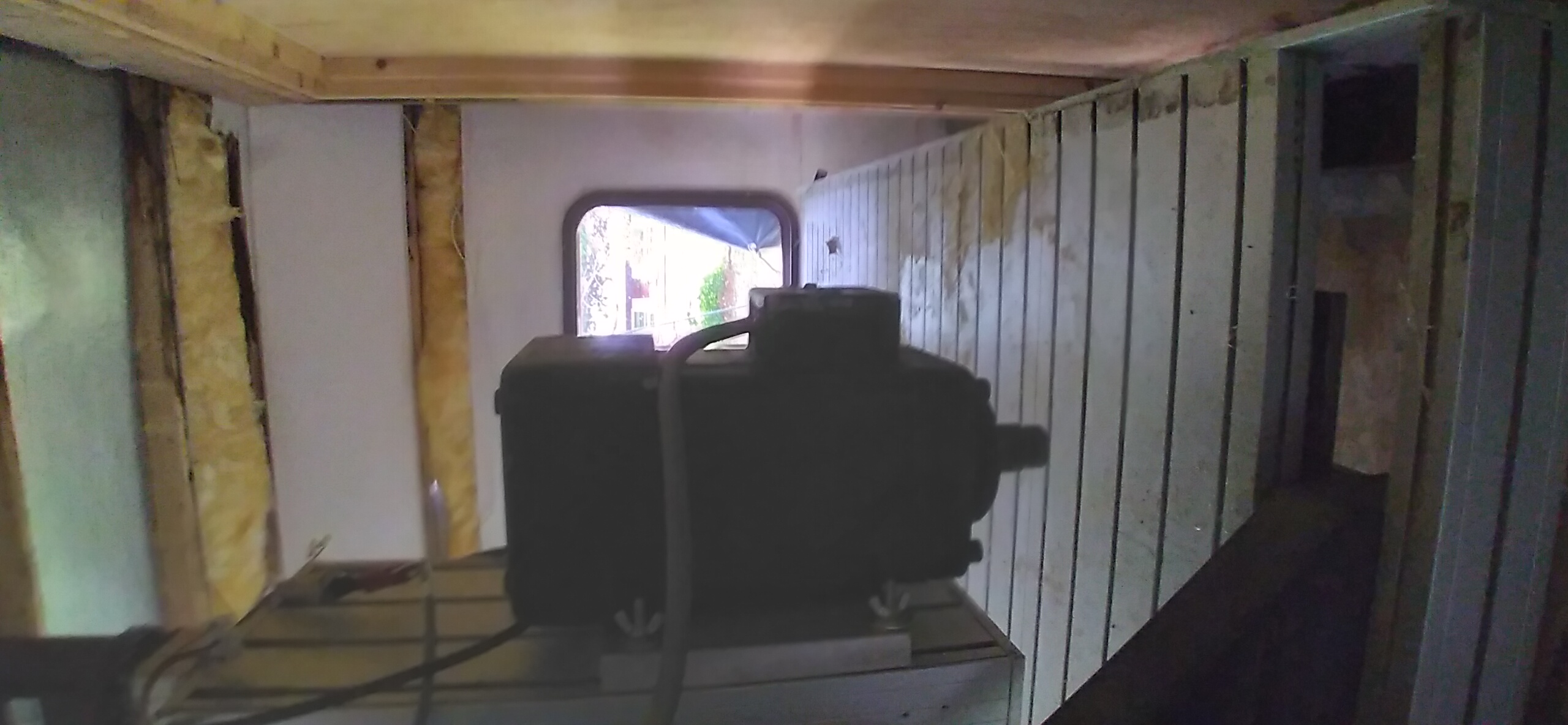
the new CNC shed build is halted temporarily, but in a condition to survive the Maine winter well.
the machine itself works still, last i knew, but i have not been able to get out there and prep it for possible long term storage, like greasing the slides and screws. so i know not what condition it will be in when i can medically return to it.
i still have dreams of adding an ATC spindle to it, but those are just financial pipe-dreams right now. my priority when i return to it, will be to do some maintenance on some neglected spots, and get it to a point where i can make projects with it, and earn a little money to move forward.
i just wanted to take a moment and thank again for all the help i have received on this forum, and on the IRC/Discord. i am using my downtime to do research, in between pain and medication cycles (and occasional naps...), so when i get back to my machine, i will hopefully have a more defined plan of attack.
one thing that has constantly bugged me, is how the Z axis box is mounted. it places it right in the way... i mean, under the gantry beam, i think there is like 5 or 6 inches of clearance. my theory is, when the Z is at it's lowest usable position, the shortest tool should be at a height where it is through the spoilboard, but above the spoilboard fasteners. and when Z is at it's tallest height, it should clear the material under the gantry completely. as it is right now, the Z axis box riding up and down, it limits my material clearance, depending on the Z height position. not ideal...
i would like to remove the axis box (for Z and X) face covers so i can get in for lube and cleaning, and replace them with something easier to remove, or just leave them open (less ideal option).
really, i need a metal mill, so i can make modifications to my machine better... like milling bolt mounts through the back of the Z box to flip the mounting to the X axis... (thinking out loud...)
so, i have done a lot to this machine to get it where it is, but i have much to do to make it more ideal. i have no regrets in buying this machine, as i have learned much (i think...), but i do have a few regrets in how much wrong hardware/electronics i bought for it in the past due to little or no research before purchace (my biggest issue). but without those mistakes, i would have missed the many lessons.
Please Log in or Create an account to join the conversation.
- travis036
-
Topic Author
- Offline
- Elite Member
-
Less
More
- Posts: 283
- Thank you received: 32
15 Oct 2022 19:48 #254191
by travis036
Replied by travis036 on topic about my 48" X 48" X 5" Techno/ISEL woodworking router build
A thought occurred to me, in regard to the Z axis box being in the way... what will i use this machine for??? i doubt i will be doing thick-stock, deep reach carving... i will be doing mainly panels, flat panels. so really, the spindle only needs to be height-set on the Z box for just a little reach deeper than the collet, so that it all clears clamp fixtures. issue SOLVED.
my next thought agenda, is figuring out the vacuum dust shoe. the Perske spindle doesn't seem to support clamping one on, so i will have to design a shoe that attaches to the Z box.
i found a website that sells T-track fasteners that actually fit my Techno/ISEL table.
(www.isel-us.com/t-nuts-for-structural-extrusions.htm for anybody with a similar machine)
i have also been brainstorming safety shields around the machine for if it breaks and throws a bit, or anything else. originally, i had an overly complex idea... as i usually do. but when it comes down to ease of use, just a folding stand-up screen will work for my needs. get the machine setup, move screen for protection, hit GO, and observe through Lexan, without fear of a 20Krpm bit flying into my face.
as to why i put my new CNC shed to sleep for the winter: my funding ran out as the Federal IRS seems to be holding my return hostage, in delayed status. so i can't order more material if the current material hasn't been paid for (company credit, not store credit. the store has been paid)
also, as i am recovering from a medical operation, i am not permitted to lift more than 10 - 15 pounds. so unless i heal quick and get my tax return soon, i am running out of good weather to work on the shed before snow flies.
Please Log in or Create an account to join the conversation.
- Todd Zuercher
-

- Away
- Platinum Member
-

Less
More
- Posts: 4757
- Thank you received: 1459
18 Oct 2022 20:28 #254462
by Todd Zuercher
Replied by Todd Zuercher on topic about my 48" X 48" X 5" Techno/ISEL woodworking router build
I've never experienced tooling being violently thrown from a router when it breaks. In wood working it is much more likely that the material you are milling might break or come loose from its fixture and be thrown out at high speed. That I have seen happen numerous times. But broken tooling generally doesn't go flying.
The following user(s) said Thank You: tommylight, travis036
Please Log in or Create an account to join the conversation.
- travis036
-
Topic Author
- Offline
- Elite Member
-
Less
More
- Posts: 283
- Thank you received: 32
03 Dec 2022 12:26 #258419
by travis036
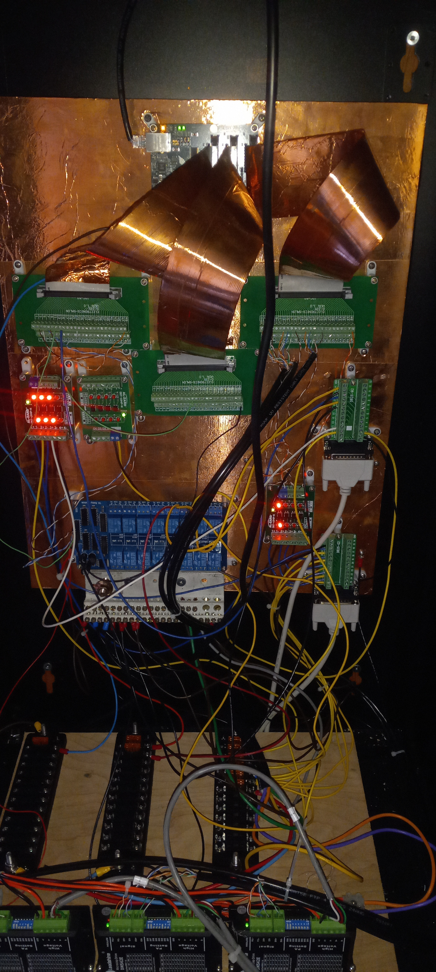
I have been working to improve the wiring in my control cabinet. so far i have replaced the un-fused power taps with fuse blocks, and replaced the separate scattered grounds with a single ground block (my method of a star-ground).
my next task will be to route the wires a little better, and clean up the arrangement of connections between the control box and machine, via the 25-pin parallel port cables. i have a enclosure for the machine-side junction box.
Replied by travis036 on topic about my 48" X 48" X 5" Techno/ISEL woodworking router build
I have been working to improve the wiring in my control cabinet. so far i have replaced the un-fused power taps with fuse blocks, and replaced the separate scattered grounds with a single ground block (my method of a star-ground).
my next task will be to route the wires a little better, and clean up the arrangement of connections between the control box and machine, via the 25-pin parallel port cables. i have a enclosure for the machine-side junction box.
Attachments:
Please Log in or Create an account to join the conversation.
- travis036
-
Topic Author
- Offline
- Elite Member
-
Less
More
- Posts: 283
- Thank you received: 32
10 Dec 2023 18:45 #287781
by travis036
Replied by travis036 on topic about my 48" X 48" X 5" Techno/ISEL woodworking router build
haven't posted in a while... haven't even turned on my machine in a while.
I have been having tremors, and bumping into stuff. not certain the cause, but i had a brain MRI just last friday (Dec 8th), and am waiting on the doc to say what was found as i cannot interpret the exact findings in the radiology notes. may be something, may be nothing. current gear of thought is the onset of Parkinson's, but they are still running tests.
but i find this all a bit scary, and i question if it is even safe to turn on my machine, let alone ME run it. maybe it is just a bad inner ear infection that will clear up, and i will be good to go.
in any case, i am still making plans to use it for carving wood signs. as making plans to sell it, is giving up, and i am not ready for that yet.
worst part is, i am forgetting what i have learned by not using it. i really need to study the configs and routines again. at the very least, i should make up some general setup check-list, to refresh my memory. perhaps i just had a mental scare, and i just need to jump back in, starting slow and precise, to get back into it.
i know for a fact i will have to run-in my spindle again, to ensure the bearings are still in good shape after sitting.
anyway, just wanted to update a little bit.
Please Log in or Create an account to join the conversation.
- travis036
-
Topic Author
- Offline
- Elite Member
-
Less
More
- Posts: 283
- Thank you received: 32
05 Mar 2024 13:46 #295229
by travis036
Replied by travis036 on topic about my 48" X 48" X 5" Techno/ISEL woodworking router build
thinking of yet another re-wire... why you ask? when it works you ask? because the wiring is hap-hazard and hard to debug, is the answer. i have made so many changes that my schematics no longer correlate to my wiring, and that is not future-proof for the next guy.
my plan this time is to actually have rules i want to follow, and to label everything. then i want a master book that tells what every wire, relay, and junction is for. yeah, it may take longer to get back up and running. but it will be safer, and reliable. no more wires twisted together and taped up in random places i forgot about.
also, i need to make a way to lube the machine. take this last video i did of my machine:
the Z and X axis are boxed in. so i need to create access to the slides and screws for lube. Y axis i can get by climbing under the machine. and as this is a woodworking router, i can't have oil and grease dripping, so i need to be able to clean the old grease off before adding a film of new grease. (i forget what the exact grease is, Mobile 1 Extreme Pressure?)
i have thought of taking the covers for the slides right off and making removable covers, or bellows.
all this will have to wait for the new shop to be finished. still working on raising funds. collecting bottles, pan-handeling... the usual story. not expecting a huge tax refund this year, but every penny is planned to go toward the shop. if i can get a wall to mount my furnace, and a wall for my entry door, the rest should fall into place. i plan on building the entry door rather than buying one, as it is just cheaper. then it is just a matter of dragging the electrical service over from the current shop, and moving the machine.
i just hope that the nearby dead cherry tree does not fall on my new shop, as i have not the money to have it taken down...
my plan this time is to actually have rules i want to follow, and to label everything. then i want a master book that tells what every wire, relay, and junction is for. yeah, it may take longer to get back up and running. but it will be safer, and reliable. no more wires twisted together and taped up in random places i forgot about.
also, i need to make a way to lube the machine. take this last video i did of my machine:
the Z and X axis are boxed in. so i need to create access to the slides and screws for lube. Y axis i can get by climbing under the machine. and as this is a woodworking router, i can't have oil and grease dripping, so i need to be able to clean the old grease off before adding a film of new grease. (i forget what the exact grease is, Mobile 1 Extreme Pressure?)
i have thought of taking the covers for the slides right off and making removable covers, or bellows.
all this will have to wait for the new shop to be finished. still working on raising funds. collecting bottles, pan-handeling... the usual story.
not expecting a huge tax refund this year, but every penny is planned to go toward the shop. if i can get a wall to mount my furnace, and a wall for my entry door, the rest should fall into place. i plan on building the entry door rather than buying one, as it is just cheaper. then it is just a matter of dragging the electrical service over from the current shop, and moving the machine.i just hope that the nearby dead cherry tree does not fall on my new shop, as i have not the money to have it taken down...
Please Log in or Create an account to join the conversation.
Time to create page: 0.194 seconds