Taig CNC Mill Upgrades: Probe, Spindle, Pendant, etc..
- nf1z
- Offline
- New Member
-

Less
More
- Posts: 19
- Thank you received: 8
28 Jan 2021 08:33 #196908
by nf1z
Taig CNC Mill Upgrades: Probe, Spindle, Pendant, etc.. was created by nf1z
After getting back to my Taig CNC mill after a few years, I decided to make a few overdue improvements. I changed from a parallel port to a 7I76e, added a pendant/MPG liberated from a commercial machine, added a tool length measurement (TLM) system, and a speed-controlled spindle. I also moved from Axis to Gmoccapy. The whole thing was integrated into a new enclosure with a new SMPS. The 7I76e and pendant required little work to incorporate, mostly just applying existing HAL components and some integration work. The TLM required making a probe and remapping the M6 code. That mostly followed the published guidelines but I think it has a few unique features, so I will describe it in a separate forum topic. The speed-controlled spindle was by far the biggest effort, requiring changes to the Taig (though nothing drastic or irreversible) as well as significant new hardware and a new HAL component. I will describe the hardware here, but the HAL component will be described in a separate topic; hopefully, this will make the information more digestible.
Tool Probe:
For the TLM, a hardware probe switch for the LinuxCNC G38.2 code was required. There are several designs around, including some "zero" designs that use the conductivity of the tool and the work, or force-measuring resistors interposed between tool tip and work. The 3D printing world uses many such cheap and cheerful devices with complex software for auto-levelling and nozzle height calibration, but my experience of them is that they are mostly not very accurate or reliable. My current printer uses solid rigid structures and old school measuring and adjusting methods to get the required accuracy, which works very well unless the tool (nozzle) needs to be changed frequently. For the Taig, I needed a system that worked with multiple tools and work offsets, and didn't want complex software, so I adopted the approach of many commercial machines that use a high quality switch in an accurately known location. This allows tool offsets to be independent of work coordinates. It also provides for tool measuring inside a program, though this is secondary. Commercially, tools are generally in holders such as the CAT40 type, so tool offsets are completely repeatable when tools are changed. Tools can be measured once only, during job setup (or they might be touched off manually if there is no TLM sensor). TLM done inside a program is used mainly for tool breakage detection and wear adjustment using deliberately-inserted special M-codes. In my case, with the standard ER16 spindle, I have no effective way to reload random tools with the same offset, so I do TLM after each tool change, as part of the M6 code. This requires an accurate probe switch in a fixed (or at least known) location, and why I remapped M6.
Some of the commercial mills have complex laser beam systems, but many of the commercial mills use a simple plunger fixed to the table that activates proximity switches. In lathes, there is less room, so one popular solution is the Omron-style 4 switch unit that is not much more than an inch cube in size. They are pretty pricey, well built, and highly accurate, but the sensors don't like high-speed contact with lathe tools, so it's easy to find a smashed unit with some of the sensors still good. I pressed out one of these (carefully), pressed it into a small piece of aluminium and bolted it to the Taig table. Channels milled underneath bring out a coaxial audio cable to the CNC probe input.
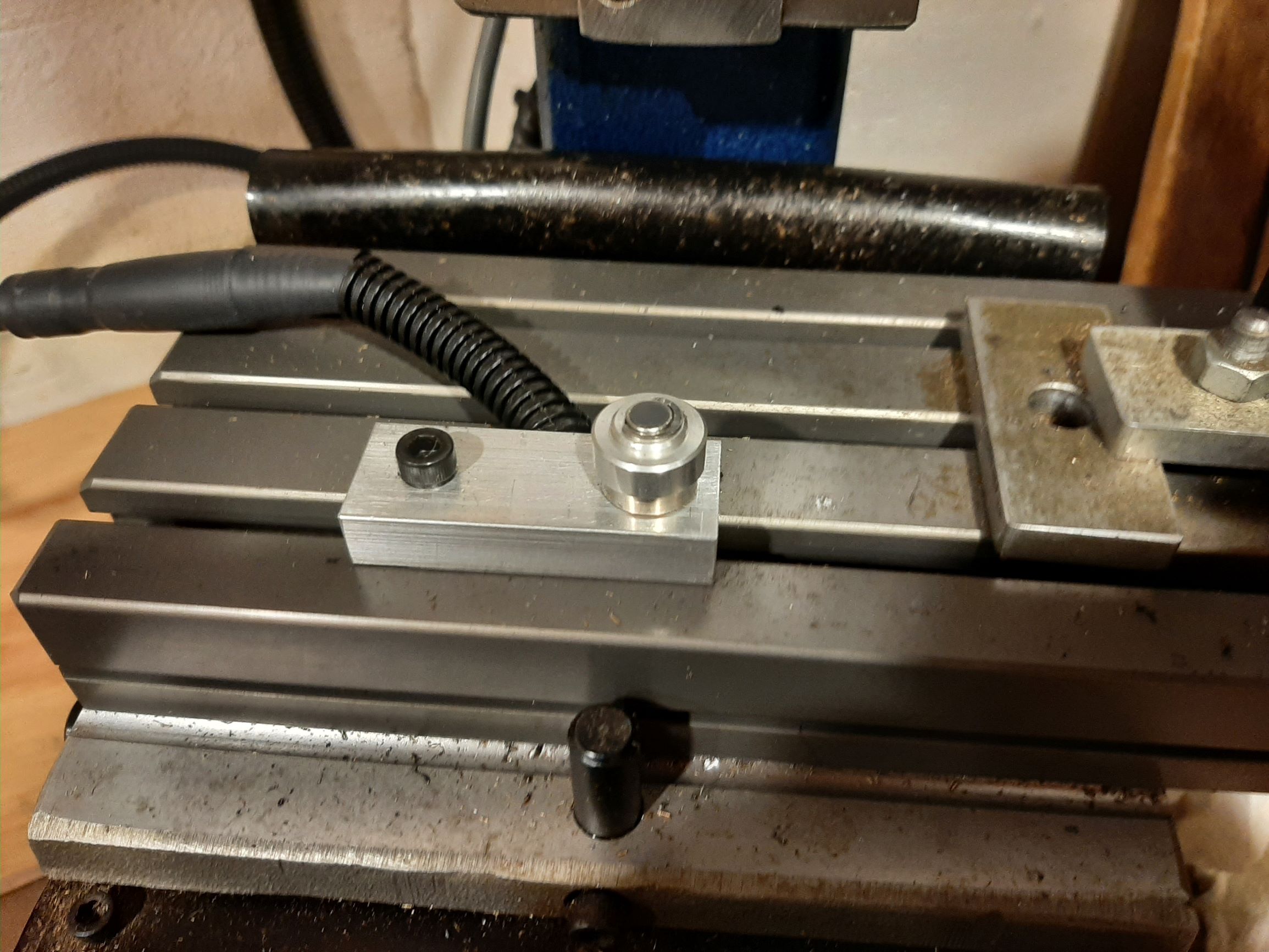
Tool probe attached to the Taig table. The small contact button on top is about 4mm diameter carbide. Note how well protected is the switch (Hint: you can't see it at all!)
I've tested the repeatability of the switch and it is better than .0002". It's probably better than in the average lathe, because the permanent mounting to the table is more rigid. Incidentally, some of the cheap mechanical micro switches are surprisingly accurate, for at least some of their life, so would make good sensors - but protecting them from chips and such would not be easy. I found they worked very well in the first 3D printer auto-level Z probe I built.
For control, I added a simple side panel to Gmoccapy. This is only really used to calibrate the probe at power-up and show status. I also used some of the built-in Gmoccapy probe configuration functionality, but I adapted it slightly as it did not entirely match my model of operation.
Spindle:
The Taig mill is incredibly mechanically solid for its size, and the CNC-ready version is easily made into a CNC mill with a few steppers in just a couple of hours. It is to my mind the only affordable option for a desktop CNC mill capable of doing real work (up to it's size limits, of course). Possibly the Sherline is a competitor, but I have no experience of it. I did own a MAXNC mill for while, but it was too small, the structure was flimsy and the axis drive components were a joke. The standard spindle motor of the Taig is powerful enough (1/4 HP, 185W), but massive (something like 15lbs hanging on the Z carriage) and fixed speed with 6-step pulleys. It is in my opinion the most restricting point in the basic design, though upgraded spindle drives are commercially available. After some research, I came across the ODrive , a dual motor controller for low-cost BLDC motors, such as are used in model aircraft and vehicles. BLDC motors are attractive for their wide controllable speed range and high power/weight ratio, as well as low cost. After playing with it for a while, I installed the ODrive, a BLDC motor and encoder on the Taig, and wrote a HAL component to provide VFD-like functions. I will describe the HAL component in a separate topic, and only describe the hardware here.
The ODrive is a PCB-level device, based on an STM32 microcontroller, designed for position control as well as velocity control of two motors, and can be used to replace servos or steppers. The position control makes it attractive for functions like spindle orientation and as a lathe C-axis for mill-turning operations. Currently my HAL component is a VFD, although it does provide position feedback and supports synchronized tapping. As a word of warning, I initially obtained a China clone which supported only one motor, to save space, but it had no regeneration handling, so was useless. I had some entertainment getting my money back.
Note the ODrive project is still in development, so it's likely to have some bugs (though I have seen none so far) and some shortcomings, but is also likely to become better. I have no affiliation with this organization.
Choosing components for a new project sometimes presents problems in establishing clear requirements that are achievable within cost and availability constraints. My desire was that the speed controlled motor provide at least as much power to the spindle as the existing motor, throughout the range of speeds from 1000 to 10,000 RPM, on the basis that I knew the Taig motor was adequate to the type of tasks it could handle. By definition and ignoring losses, a 1/4HP motor at full load provides 0.5 N-m torque at 3540 RPM. On the lowest step of the Taig pulley this becomes 1.5 N-m at 1200 RPM. If a speed-controlled motor is capable of providing that much torque at that low RPM, but is also able to reach 10,000 RPM, it could be used to directly drive the spindle, without gearing or step pulleys, as generally, the power output will increase with speed. In the end, very few available motors met these conditions, and I chose the ODrive D5065 motor with a torque of 2 N-m at maximum rated current. The fact it was a dual shaft motor to enable mounting of an encoder was actually the prime driver. With a 1.25 step up the motor can reach 10,000 RPM, making the maximum spindle torque 1.6 N-m. Thus a fixed pulley arrangement can be used to cover the entire speed range with the desired low-end torque.
Without getting into too much detail, it was decided to use a Meanwell LRS350 350W 48V SMPS to power the ODrive, or approximately twice the power required at the lowest speed. Physical size of the SMPS was a major consideration. The excess power availability will cause the maximum spindle power to be torque-limited (power will increase linearly with speed) up to the power capacity of the SMPS, and then be power-limited after that (torque will reduce). In effect, it will be a 1/2HP motor above 2000 RPM. This assumes that the ODrive second motor driver is not used.
To attach it to the Taig, I kept the same general arrangement of mounting the motor on a small plate attached to the Z carriage, driving the spindle via a belt and pulleys. I made a new plate for the BLDC motor mount dimensions and a new motor pulley (8mm bore versus 3/8"), driving one of the existing spindle pulley steps with the existing belt. The motor pulley is sized to provide the 1.25:1 step up. A CUI AMT102 encoder is mounted on the top of a 3D-printed motor enclosure and runs on the motor second shaft.
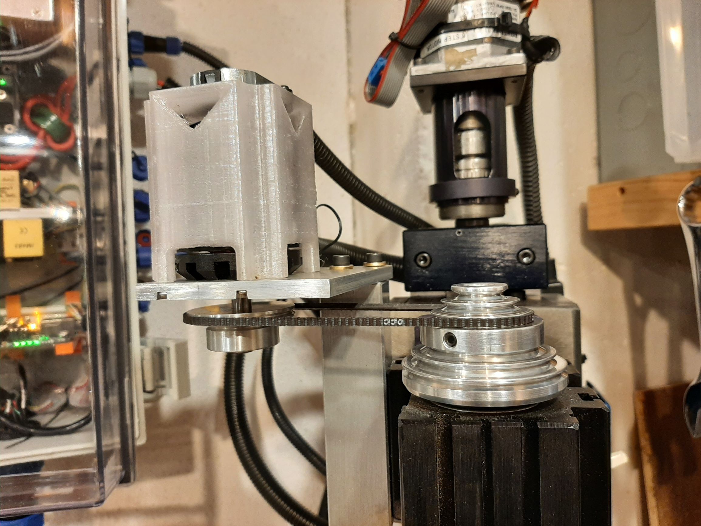
BLDC motor on mounting plate, encoder on top of 3D-printed enclosure. New pulley on bottom shaft.
The ODrive is mounted on an aluminium bracket on a DIN rail inside my recently-rebuilt CNC control enclosure, as is the 48V SMPS. I found it necessary to add a common mode choke on the motor wires to reduce noise.
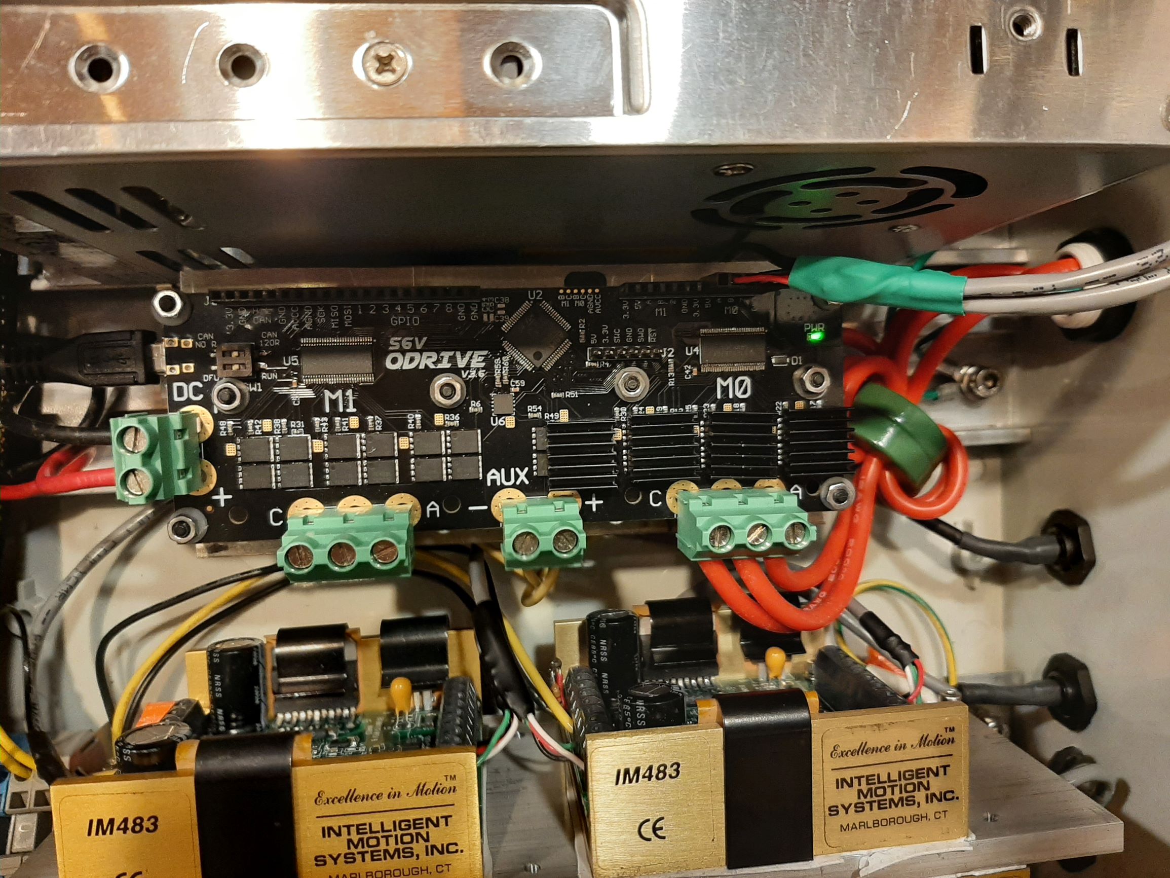
ODrive board mounted on DIN rail in control cabinet
The ODrive has several control interfaces. The so-called Native Interface is USB, and Python modules and a tool are provided to allow configuration and management from a Python prompt or script running on a PC. There is also a UART interface which accepts some simple ASCII commands, often using an Arduino as a go-between, and a CAN interface. Additionally, there are GPIO pins that can be used to provide a step-and-direction interface or analog speed control. I was initially going to use this to connect directly to the 7I76E spindle outputs, but this isn't entirely supported yet. You can do it but it requires a Python script running on the PC to read the GPIO inputs then issue USB commands back to the drive, which seems silly. Alternatively, code in the ODrive itself (C++) could be provided. My design decision was to use the Native interface for everything, so the HAL component is written in Python and uses the ODrive modules to provide the communication. The HAL component does not need to know about the USB details. Naturally a physical USB hardware interface from the PC to the ODrive is required; it would have been nice to have used the ethernet interface to the 7I76E for this instead of the USB.
The HAL component provides VFD-like functionality for both motors and feeds back position and speed information and some other stats. In order to look at this, I built a Gmoccapy embedded tab that shows spindle speed and other data. Previously, I'd only used Axis, but it looked like it would be better to use Gmoccapy to add my own GUI features. So far, I am pretty pleased with Gmoccapy and it's flexibility.
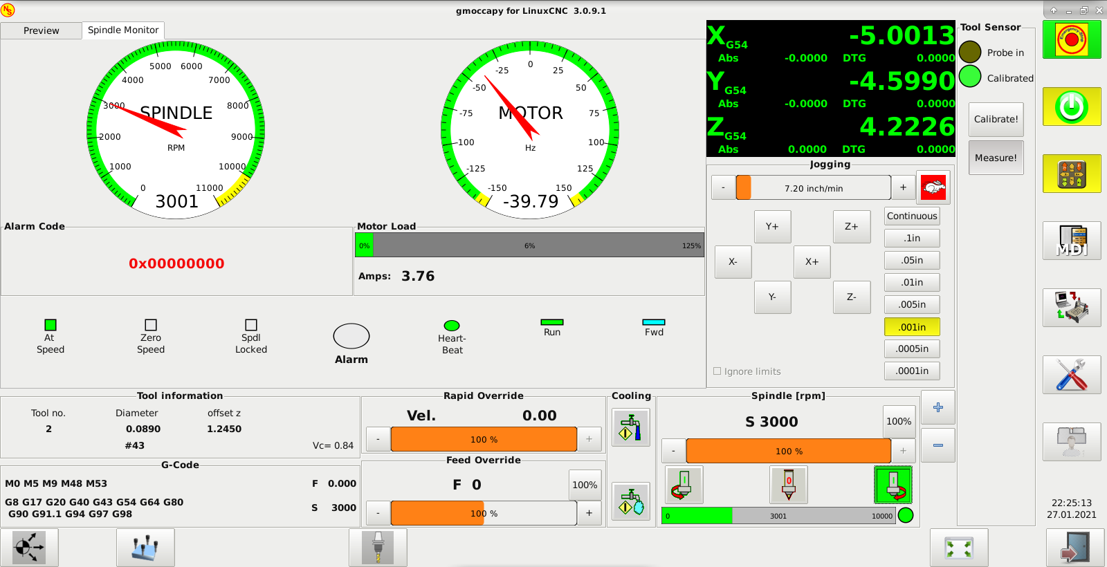
Gmoccapy "Spindle Monitor" tab. Shows spindle commanded and running at 3000 RPM forward (CW), motor going at 2387 RPM in what ODrive considers the negative direction. The motor load of 3.76A is 6% of the configured full-load amps; at 2387 RPM, it is a power level of about 33W. The "Tool Sensor" panel shows the probe is calibrated but probe is not activated.
So far, I have had no chance to perform exhaustive testing, but it does seem to have This has all been tested to some degree - I cannot say exhaustively, but the hardware and HAL component seem pretty stable. The USB interface has proved much more reliable than I had anticipated (I feared noise from the motor getting into the USB cable), so I have no plans to modify the ODrive code or use the CAN interface. I tested the synchronized tapping feature, and it seemed to work OK despite the spindle and motor (or really the encoder) not being rigidly coupled, though I found the spindle belt could slip on a large tap. This is obviously no good, so I am going to fit a timing belt rather than the rather small vee-belt. In the longer term, I will probably either move the encoder to the spindle or fit a separate spindle index sensor, so peck tapping will work.
This was a overview description of the recent modifications to my mill. If you're interested in the details of the HAL component for the ODrive, or in the M6 remapping code, look for separate topics I hope to post pretty soon. Other than that, discussion and comment is welcome.
Tool Probe:
For the TLM, a hardware probe switch for the LinuxCNC G38.2 code was required. There are several designs around, including some "zero" designs that use the conductivity of the tool and the work, or force-measuring resistors interposed between tool tip and work. The 3D printing world uses many such cheap and cheerful devices with complex software for auto-levelling and nozzle height calibration, but my experience of them is that they are mostly not very accurate or reliable. My current printer uses solid rigid structures and old school measuring and adjusting methods to get the required accuracy, which works very well unless the tool (nozzle) needs to be changed frequently. For the Taig, I needed a system that worked with multiple tools and work offsets, and didn't want complex software, so I adopted the approach of many commercial machines that use a high quality switch in an accurately known location. This allows tool offsets to be independent of work coordinates. It also provides for tool measuring inside a program, though this is secondary. Commercially, tools are generally in holders such as the CAT40 type, so tool offsets are completely repeatable when tools are changed. Tools can be measured once only, during job setup (or they might be touched off manually if there is no TLM sensor). TLM done inside a program is used mainly for tool breakage detection and wear adjustment using deliberately-inserted special M-codes. In my case, with the standard ER16 spindle, I have no effective way to reload random tools with the same offset, so I do TLM after each tool change, as part of the M6 code. This requires an accurate probe switch in a fixed (or at least known) location, and why I remapped M6.
Some of the commercial mills have complex laser beam systems, but many of the commercial mills use a simple plunger fixed to the table that activates proximity switches. In lathes, there is less room, so one popular solution is the Omron-style 4 switch unit that is not much more than an inch cube in size. They are pretty pricey, well built, and highly accurate, but the sensors don't like high-speed contact with lathe tools, so it's easy to find a smashed unit with some of the sensors still good. I pressed out one of these (carefully), pressed it into a small piece of aluminium and bolted it to the Taig table. Channels milled underneath bring out a coaxial audio cable to the CNC probe input.
Tool probe attached to the Taig table. The small contact button on top is about 4mm diameter carbide. Note how well protected is the switch (Hint: you can't see it at all!)
I've tested the repeatability of the switch and it is better than .0002". It's probably better than in the average lathe, because the permanent mounting to the table is more rigid. Incidentally, some of the cheap mechanical micro switches are surprisingly accurate, for at least some of their life, so would make good sensors - but protecting them from chips and such would not be easy. I found they worked very well in the first 3D printer auto-level Z probe I built.
For control, I added a simple side panel to Gmoccapy. This is only really used to calibrate the probe at power-up and show status. I also used some of the built-in Gmoccapy probe configuration functionality, but I adapted it slightly as it did not entirely match my model of operation.
Spindle:
The Taig mill is incredibly mechanically solid for its size, and the CNC-ready version is easily made into a CNC mill with a few steppers in just a couple of hours. It is to my mind the only affordable option for a desktop CNC mill capable of doing real work (up to it's size limits, of course). Possibly the Sherline is a competitor, but I have no experience of it. I did own a MAXNC mill for while, but it was too small, the structure was flimsy and the axis drive components were a joke. The standard spindle motor of the Taig is powerful enough (1/4 HP, 185W), but massive (something like 15lbs hanging on the Z carriage) and fixed speed with 6-step pulleys. It is in my opinion the most restricting point in the basic design, though upgraded spindle drives are commercially available. After some research, I came across the ODrive , a dual motor controller for low-cost BLDC motors, such as are used in model aircraft and vehicles. BLDC motors are attractive for their wide controllable speed range and high power/weight ratio, as well as low cost. After playing with it for a while, I installed the ODrive, a BLDC motor and encoder on the Taig, and wrote a HAL component to provide VFD-like functions. I will describe the HAL component in a separate topic, and only describe the hardware here.
The ODrive is a PCB-level device, based on an STM32 microcontroller, designed for position control as well as velocity control of two motors, and can be used to replace servos or steppers. The position control makes it attractive for functions like spindle orientation and as a lathe C-axis for mill-turning operations. Currently my HAL component is a VFD, although it does provide position feedback and supports synchronized tapping. As a word of warning, I initially obtained a China clone which supported only one motor, to save space, but it had no regeneration handling, so was useless. I had some entertainment getting my money back.
Note the ODrive project is still in development, so it's likely to have some bugs (though I have seen none so far) and some shortcomings, but is also likely to become better. I have no affiliation with this organization.
Choosing components for a new project sometimes presents problems in establishing clear requirements that are achievable within cost and availability constraints. My desire was that the speed controlled motor provide at least as much power to the spindle as the existing motor, throughout the range of speeds from 1000 to 10,000 RPM, on the basis that I knew the Taig motor was adequate to the type of tasks it could handle. By definition and ignoring losses, a 1/4HP motor at full load provides 0.5 N-m torque at 3540 RPM. On the lowest step of the Taig pulley this becomes 1.5 N-m at 1200 RPM. If a speed-controlled motor is capable of providing that much torque at that low RPM, but is also able to reach 10,000 RPM, it could be used to directly drive the spindle, without gearing or step pulleys, as generally, the power output will increase with speed. In the end, very few available motors met these conditions, and I chose the ODrive D5065 motor with a torque of 2 N-m at maximum rated current. The fact it was a dual shaft motor to enable mounting of an encoder was actually the prime driver. With a 1.25 step up the motor can reach 10,000 RPM, making the maximum spindle torque 1.6 N-m. Thus a fixed pulley arrangement can be used to cover the entire speed range with the desired low-end torque.
Without getting into too much detail, it was decided to use a Meanwell LRS350 350W 48V SMPS to power the ODrive, or approximately twice the power required at the lowest speed. Physical size of the SMPS was a major consideration. The excess power availability will cause the maximum spindle power to be torque-limited (power will increase linearly with speed) up to the power capacity of the SMPS, and then be power-limited after that (torque will reduce). In effect, it will be a 1/2HP motor above 2000 RPM. This assumes that the ODrive second motor driver is not used.
To attach it to the Taig, I kept the same general arrangement of mounting the motor on a small plate attached to the Z carriage, driving the spindle via a belt and pulleys. I made a new plate for the BLDC motor mount dimensions and a new motor pulley (8mm bore versus 3/8"), driving one of the existing spindle pulley steps with the existing belt. The motor pulley is sized to provide the 1.25:1 step up. A CUI AMT102 encoder is mounted on the top of a 3D-printed motor enclosure and runs on the motor second shaft.
BLDC motor on mounting plate, encoder on top of 3D-printed enclosure. New pulley on bottom shaft.
The ODrive is mounted on an aluminium bracket on a DIN rail inside my recently-rebuilt CNC control enclosure, as is the 48V SMPS. I found it necessary to add a common mode choke on the motor wires to reduce noise.
ODrive board mounted on DIN rail in control cabinet
The ODrive has several control interfaces. The so-called Native Interface is USB, and Python modules and a tool are provided to allow configuration and management from a Python prompt or script running on a PC. There is also a UART interface which accepts some simple ASCII commands, often using an Arduino as a go-between, and a CAN interface. Additionally, there are GPIO pins that can be used to provide a step-and-direction interface or analog speed control. I was initially going to use this to connect directly to the 7I76E spindle outputs, but this isn't entirely supported yet. You can do it but it requires a Python script running on the PC to read the GPIO inputs then issue USB commands back to the drive, which seems silly. Alternatively, code in the ODrive itself (C++) could be provided. My design decision was to use the Native interface for everything, so the HAL component is written in Python and uses the ODrive modules to provide the communication. The HAL component does not need to know about the USB details. Naturally a physical USB hardware interface from the PC to the ODrive is required; it would have been nice to have used the ethernet interface to the 7I76E for this instead of the USB.
The HAL component provides VFD-like functionality for both motors and feeds back position and speed information and some other stats. In order to look at this, I built a Gmoccapy embedded tab that shows spindle speed and other data. Previously, I'd only used Axis, but it looked like it would be better to use Gmoccapy to add my own GUI features. So far, I am pretty pleased with Gmoccapy and it's flexibility.
Gmoccapy "Spindle Monitor" tab. Shows spindle commanded and running at 3000 RPM forward (CW), motor going at 2387 RPM in what ODrive considers the negative direction. The motor load of 3.76A is 6% of the configured full-load amps; at 2387 RPM, it is a power level of about 33W. The "Tool Sensor" panel shows the probe is calibrated but probe is not activated.
So far, I have had no chance to perform exhaustive testing, but it does seem to have This has all been tested to some degree - I cannot say exhaustively, but the hardware and HAL component seem pretty stable. The USB interface has proved much more reliable than I had anticipated (I feared noise from the motor getting into the USB cable), so I have no plans to modify the ODrive code or use the CAN interface. I tested the synchronized tapping feature, and it seemed to work OK despite the spindle and motor (or really the encoder) not being rigidly coupled, though I found the spindle belt could slip on a large tap. This is obviously no good, so I am going to fit a timing belt rather than the rather small vee-belt. In the longer term, I will probably either move the encoder to the spindle or fit a separate spindle index sensor, so peck tapping will work.
This was a overview description of the recent modifications to my mill. If you're interested in the details of the HAL component for the ODrive, or in the M6 remapping code, look for separate topics I hope to post pretty soon. Other than that, discussion and comment is welcome.
Attachments:
The following user(s) said Thank You: tommylight, kapucin
Please Log in or Create an account to join the conversation.
- tommylight
-

- Offline
- Moderator
-

Less
More
- Posts: 21697
- Thank you received: 7414
01 Feb 2021 09:37 #197294
by tommylight
Replied by tommylight on topic Taig CNC Mill Upgrades: Probe, Spindle, Pendant, etc..
Moved to "show your stuff" as requested.
The following user(s) said Thank You: nf1z
Please Log in or Create an account to join the conversation.
Time to create page: 0.252 seconds