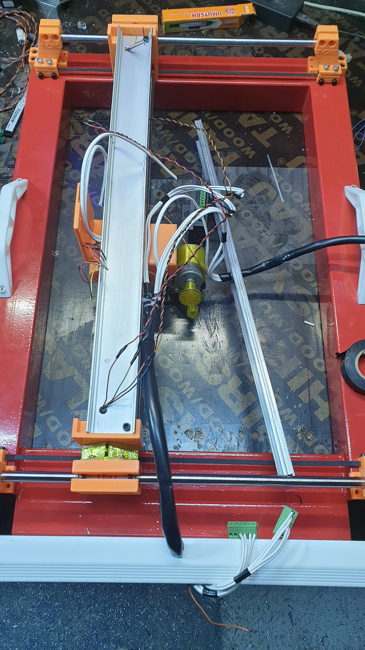
New design for a CNC engraver/etcher/scratcher ... ???
- tommylight
-
 Topic Author
- Away
- Moderator
-

Less
More
- Posts: 21134
- Thank you received: 7220
27 Aug 2022 20:47 #250595
by tommylight
New design for a CNC engraver/etcher/scratcher ... ??? was created by tommylight
What the tiiiiiit is this thing supposed to be named?
I am going with "scratcher" from now on, all it does is scratch the surface of granite or stone or glass or wood or...
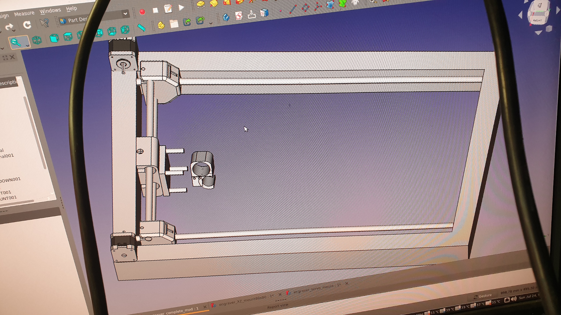
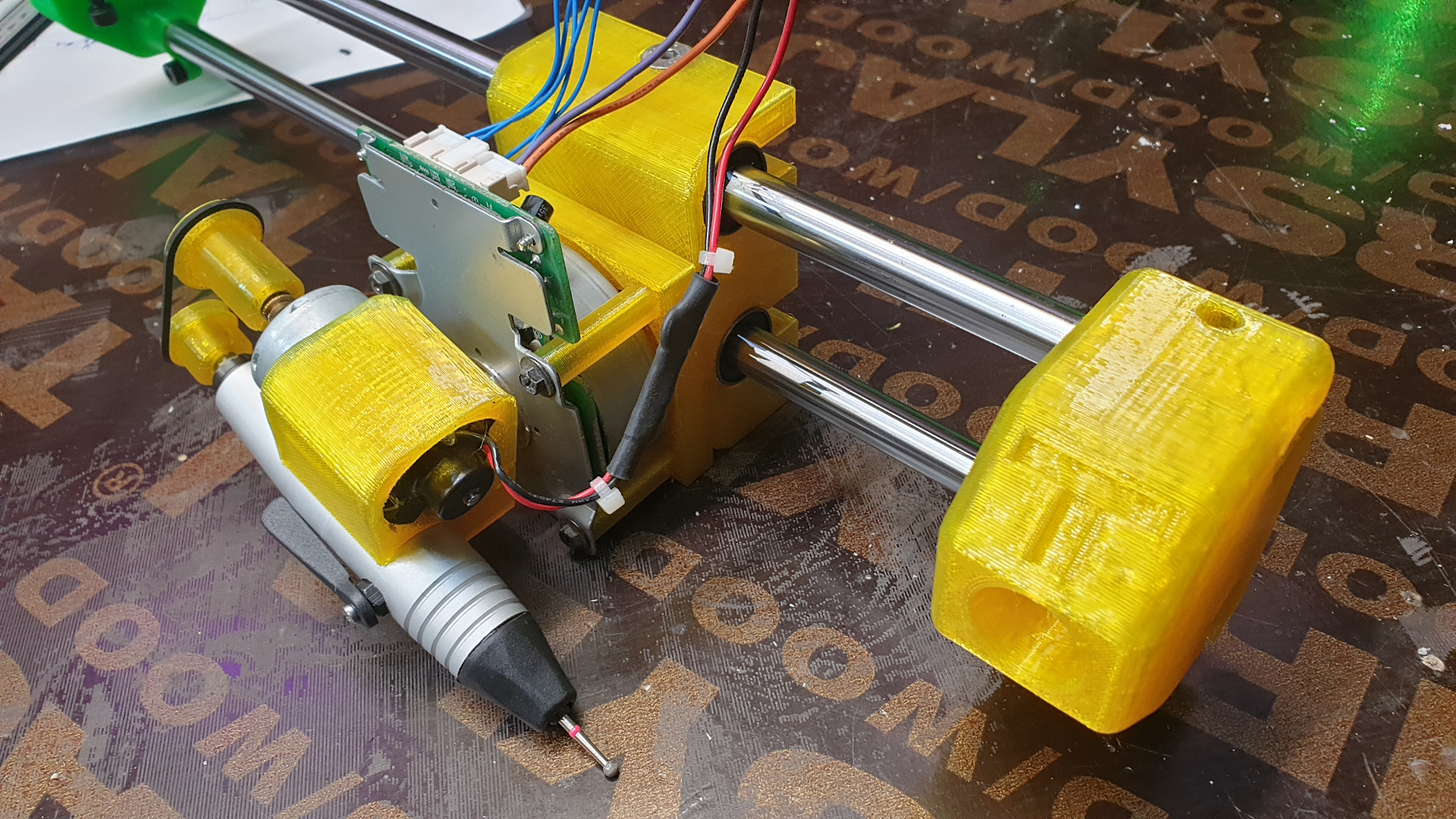
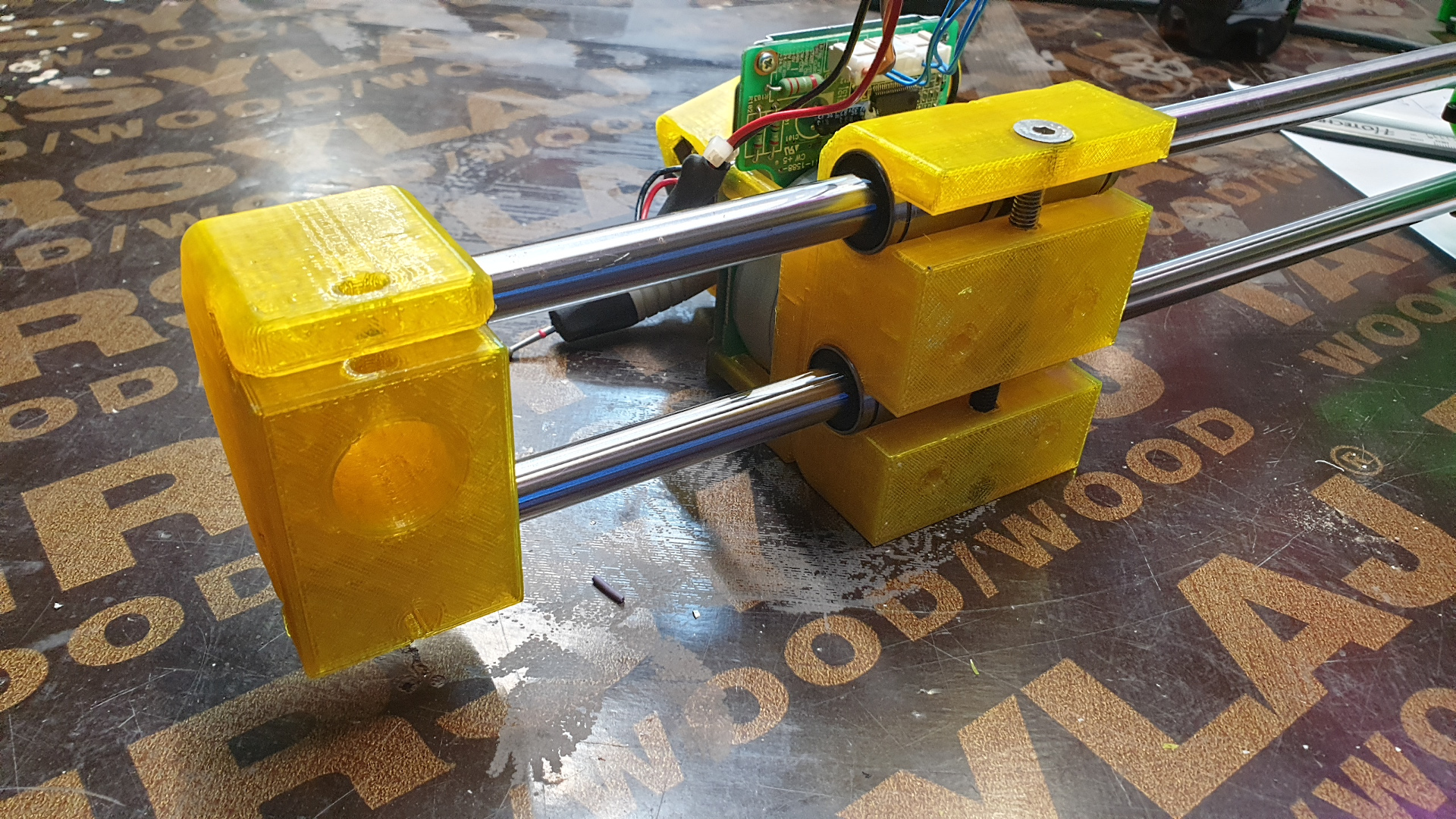
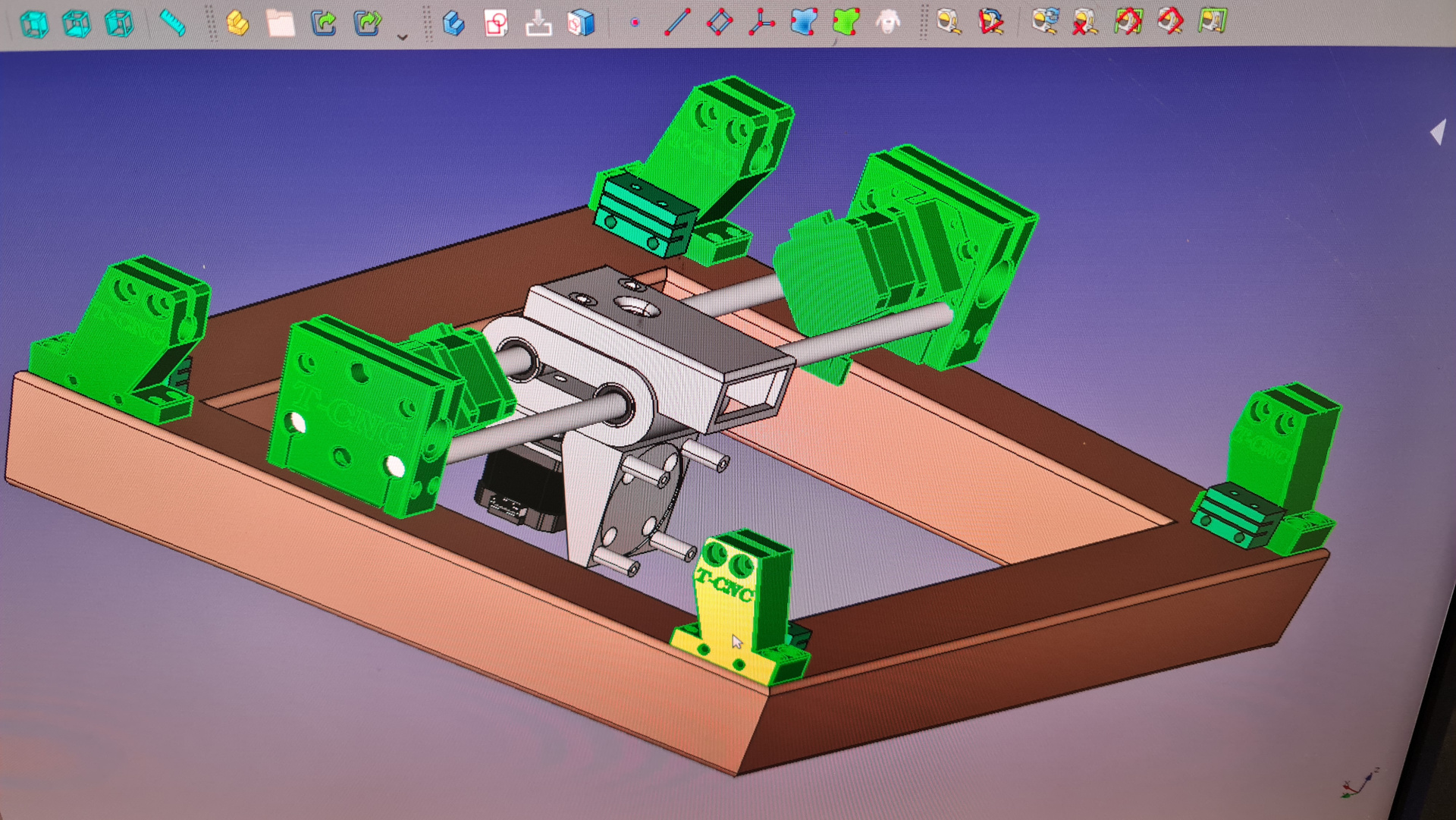
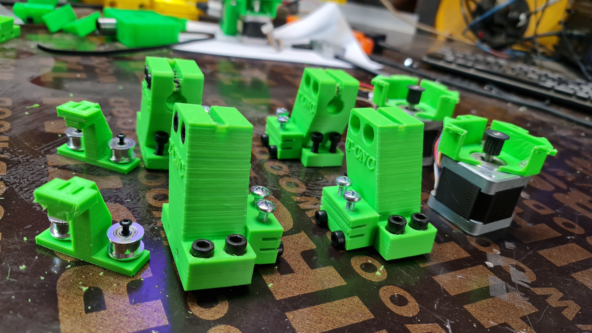
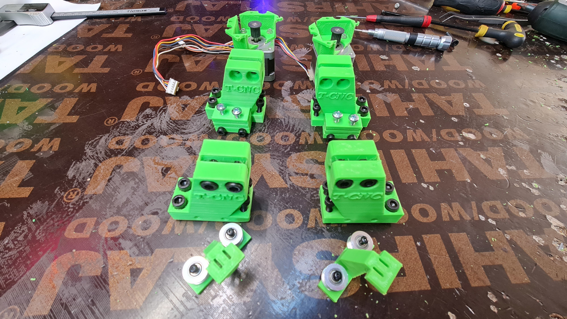
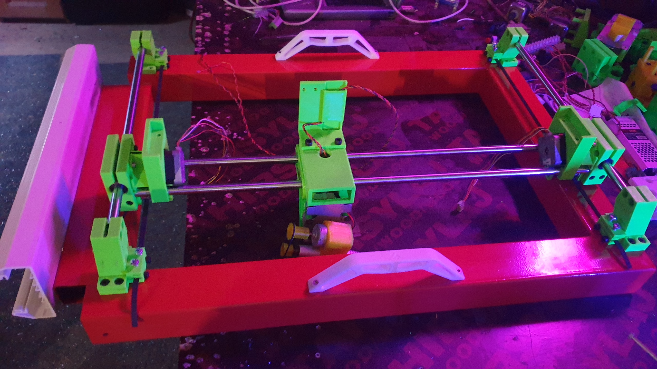
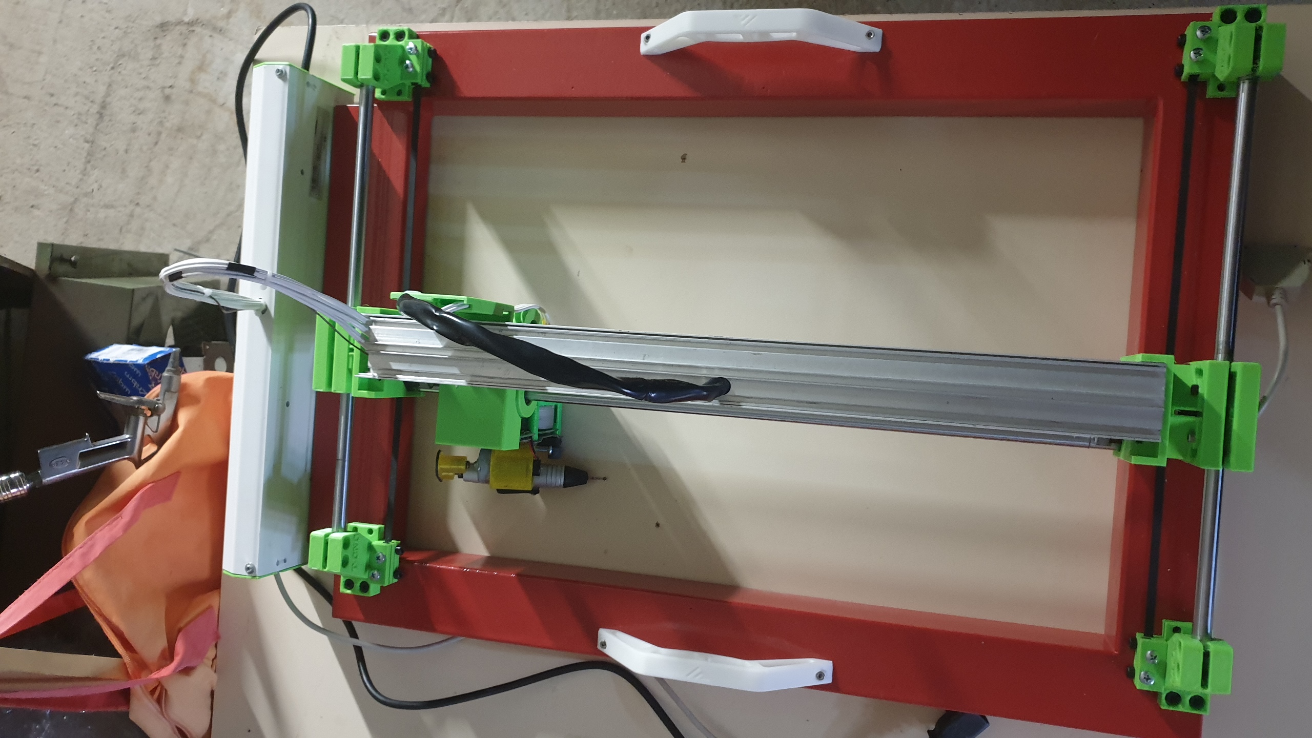
So, i thought it would be nice to do a new design for these machines i keep making from time to time and since i had to learn FreeCAD again, i gave it a go, so here are the results of the Version 1 :
and Version 2 :
Attachments:
The following user(s) said Thank You: snowgoer540, itsme, Krist
Please Log in or Create an account to join the conversation.
- tommylight
-
 Topic Author
- Away
- Moderator
-

Less
More
- Posts: 21134
- Thank you received: 7220
27 Aug 2022 21:05 - 06 Jun 2024 20:31 #250596
by tommylight
Replied by tommylight on topic New design for a CNC engraver/etcher/scratcher ... ???
For more info and videos
Instagram :
www.instagram.com/toma.cnc/
www.instagram.com/toma.3d/
www.instagram.com/toma.pc/
Youtube :
www.youtube.com/@toma.cnc1
www.youtube.com/@toma.3d
www.youtube.com/@tomapc
-
Attached is the full set of STL files in case anyone wants to build one, one part is compressed using 7Z and renamed to be able to upload, so remove ".txt" before unzipping it.
Edit:
Added the latest config as it has provisions for disabling PWM on ESC/Stop to prevent spindle from making a big hole on the material. Also "run from here" should work as is.
Edit 2:
Pressure motor info:
The "pressure" motor is :
-a 3 phase BLDC motors with it's own electronic controller taken out of the old photocopiers,
-there are many versions and sizes of them,
-form 5 to 10 pins,
-all signaling is sinking type or "active low", meaning connect to ground to activate
-all have the pinout printed on the board,
-older ones are pure PWM while new ones require also a clock signal,
-some are single direction while some are bidirectional,
-and most of them can be easily used for this purpose/machine,
--The PWM ones require 5V, 12-24V and an inverted PWM signal
--The ones requiring clock signal have a self check feature, so mostly work with only 12-24V supply and one of the pins tied to ground, this pin will spin the motor for about 2 second and stop, and has to be disconnected and reconnected to spin again. This pin is used as inverted PWM but scaling must be set to about max 85-95% PWM to keep the controller from tripping and stopping the motor after 2 seconds.
--for inverting the PWM pin i use a single 220 OHm resistor and a single transistor, any NPN transistor works, resistor connected between base of transistor and PWM output from PC or Mesa board.
Last edit: 06 Jun 2024 20:31 by tommylight. Reason: more info.
The following user(s) said Thank You: phillc54, Clive S, snowgoer540
Please Log in or Create an account to join the conversation.
- phillc54
-

- Offline
- Platinum Member
-

Less
More
- Posts: 5711
- Thank you received: 2093
28 Aug 2022 01:51 #250599
by phillc54
Replied by phillc54 on topic New design for a CNC engraver/etcher/scratcher ... ???
That is cool Tommy, I like "scratcher".
The following user(s) said Thank You: tommylight
Please Log in or Create an account to join the conversation.
- tommylight
-
 Topic Author
- Away
- Moderator
-

Less
More
- Posts: 21134
- Thank you received: 7220
01 Sep 2022 21:58 #250950
by tommylight
Replied by tommylight on topic New design for a CNC engraver/etcher/scratcher ... ???
Attachments:
The following user(s) said Thank You: phillc54
Please Log in or Create an account to join the conversation.
- tommylight
-
 Topic Author
- Away
- Moderator
-

Less
More
- Posts: 21134
- Thank you received: 7220
06 Sep 2022 22:46 #251362
by tommylight
Replied by tommylight on topic New design for a CNC engraver/etcher/scratcher ... ???
Attachments:
Please Log in or Create an account to join the conversation.
- tommylight
-
 Topic Author
- Away
- Moderator
-

Less
More
- Posts: 21134
- Thank you received: 7220
20 Sep 2022 00:20 #252372
by tommylight
Also finished this working occasionally on it
It has 4 motors on the Z axis so it probes 4 corners and adjusts each corner to make the table flat.
Replied by tommylight on topic New design for a CNC engraver/etcher/scratcher ... ???
Also finished this working occasionally on it
It has 4 motors on the Z axis so it probes 4 corners and adjusts each corner to make the table flat.
Please Log in or Create an account to join the conversation.
- tommylight
-
 Topic Author
- Away
- Moderator
-

Less
More
- Posts: 21134
- Thank you received: 7220
28 Mar 2023 20:06 - 28 Mar 2023 20:08 #267727
by tommylight
Replied by tommylight on topic New design for a CNC engraver/etcher/scratcher ... ???
Another video
youtube.com/shorts/mPyvLKJxuzI?feature=share
STL files are attached near the top, if anyone wants to build one.
youtube.com/shorts/mPyvLKJxuzI?feature=share
STL files are attached near the top, if anyone wants to build one.
Last edit: 28 Mar 2023 20:08 by tommylight. Reason: added link
The following user(s) said Thank You: Clive S, spumco
Please Log in or Create an account to join the conversation.
- santy
- Offline
- Premium Member
-

Less
More
- Posts: 117
- Thank you received: 10
11 Nov 2023 16:49 #285113
by santy
Replied by santy on topic New design for a CNC engraver/etcher/scratcher ... ???
Hey Tommy. I'm looking for some information on this post to help a friend build a similar machine.
I'm trying to understand the used mechanism to allow for harder/softer engraving. Are you using a faster motor speed for the darker areas? Or pressing harder with a Z axis movement? This is my main question in the proccess.
I managed to install dmap2gcode which is really helpful here!
I'm trying to understand the used mechanism to allow for harder/softer engraving. Are you using a faster motor speed for the darker areas? Or pressing harder with a Z axis movement? This is my main question in the proccess.
I managed to install dmap2gcode which is really helpful here!
Please Log in or Create an account to join the conversation.
- tommylight
-
 Topic Author
- Away
- Moderator
-

Less
More
- Posts: 21134
- Thank you received: 7220
11 Nov 2023 22:00 #285136
by tommylight
The spindle and spindle motor are attached to the shaft of a 3 phase sensored servo motor from big photocopiers, they need 12-24V to work and a inverted PWM output from parallel port or Mesa board. Inverting is done using a single resistor and a transistor.
Inverting can be done by inverting the pin in hal, but that has the nasty habit of ramming the spindle in the table until LinuxCNC is started.
Replied by tommylight on topic New design for a CNC engraver/etcher/scratcher ... ???
This.Or pressing harder with a Z axis movement?
The spindle and spindle motor are attached to the shaft of a 3 phase sensored servo motor from big photocopiers, they need 12-24V to work and a inverted PWM output from parallel port or Mesa board. Inverting is done using a single resistor and a transistor.
Inverting can be done by inverting the pin in hal, but that has the nasty habit of ramming the spindle in the table until LinuxCNC is started.
The following user(s) said Thank You: Clive S
Please Log in or Create an account to join the conversation.
- santy
- Offline
- Premium Member
-

Less
More
- Posts: 117
- Thank you received: 10
11 Nov 2023 23:51 #285142
by santy
Replied by santy on topic New design for a CNC engraver/etcher/scratcher ... ???
Oh, so Z axis only serves the purpose of probing the material. The rest is done via spindle output.
I assume the Z output from the Gcode signal is script-converted into a S1 - S1000 signal to drive the pwm out.
Can you post your files? Not sure how to handle the table flattening probe.
Thank you in advance.
I assume the Z output from the Gcode signal is script-converted into a S1 - S1000 signal to drive the pwm out.
Can you post your files? Not sure how to handle the table flattening probe.
Thank you in advance.
Please Log in or Create an account to join the conversation.
Time to create page: 0.337 seconds

