Geometry error compensation
09 Feb 2013 19:21 #29803
by f1oat
Geometry error compensation was created by f1oat
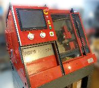
On my mini CNC milling machine ( cnc.f1oat.org ), I have a small geometry error on the X/Y table:
When the Y axis is traveling from min to max (125 mm) I experience a slope of 0.1 mm on Z.
Is there any way to compensate this defect by software ? May be with a special HAL configuration ?
Thanks.
Frederic.
When the Y axis is traveling from min to max (125 mm) I experience a slope of 0.1 mm on Z.
Is there any way to compensate this defect by software ? May be with a special HAL configuration ?
Thanks.
Frederic.
Please Log in or Create an account to join the conversation.
09 Feb 2013 21:05 #29805
by alan_3301
Replied by alan_3301 on topic Geometry error compensation
I'm still researching it, and haven't tested, so I can't give a detailed answer, but research "probekins"
It will allow for compensating uneven Z plane.
It will allow for compensating uneven Z plane.
Please Log in or Create an account to join the conversation.

09 Feb 2013 21:18 #29806
by BigJohnT
Replied by BigJohnT on topic Geometry error compensation
Can you mechanically adjust the Y axis into parallel? This is always the best solution.
You could map the axis I think... no that won't work.
Interestingly you can rotate the Z axis but not the Y... You could just change your G code or CAM output to reflect the tilt.
John
You could map the axis I think... no that won't work.
Interestingly you can rotate the Z axis but not the Y... You could just change your G code or CAM output to reflect the tilt.
John
Please Log in or Create an account to join the conversation.
09 Feb 2013 21:36 #29807
by f1oat
Replied by f1oat on topic Geometry error compensation
Thanks, probekins looks promising !
I am also thinking about using a linear formula for Z axis driving that may looks like:
machine_Z = Z + a*X + b*Y
In my case, b = 0.1/125
I have to learn about HAL to see if that is possible
Frederic.
I am also thinking about using a linear formula for Z axis driving that may looks like:
machine_Z = Z + a*X + b*Y
In my case, b = 0.1/125
I have to learn about HAL to see if that is possible
Frederic.
Please Log in or Create an account to join the conversation.
09 Feb 2013 21:46 #29808
by f1oat
Replied by f1oat on topic Geometry error compensation
For sure, mechanical adjustment is preferable.
My table surface seems not parallel with the Y axis prismatic guide. Adjustment is not easy because guide and table are the same AU4G part. And I cannot mill the table surface because the table size is wider that the X/Y milling capacity.
I will choose better mechanical design for the next machine I will build !
Frederic.
Please Log in or Create an account to join the conversation.
09 Feb 2013 21:49 #29809
by BigJohnT
Replied by BigJohnT on topic Geometry error compensation
You can hijack the Z axis with a custom hal component like my
thc component
does to control the Z height to maintain voltage.
John
John
Please Log in or Create an account to join the conversation.
10 Feb 2013 05:04 - 10 Feb 2013 06:28 #29826
by f1oat
Replied by f1oat on topic Geometry error compensation
Thank you for all good suggestions.
My problem in now solved.
I managed to add a linear formula with "sum2" and "offset" HAL components within the following custom.hal file
# Table slope correction with linear formula
#
# Add an offset to Z axis depending on X and Y position
# XCORR and YCORR parameters define the amount of correction to be applied
# The formula is : zpos-cmd-corr = zpos-cmd + XCORR * xpos-cmd + YCORR * ypos-cmd
loadrt sum2
loadrt offset
addf sum2.0 servo-thread
addf offset.0.update-output servo-thread
addf offset.0.update-feedback servo-thread
setp sum2.0.gain0 [AXIS_2]XCORR
setp sum2.0.gain1 [AXIS_2]YCORR
setp sum2.0.offset 0
net xpos-cmd => sum2.0.in0
net ypos-cmd => sum2.0.in1
net zpos-cmd => offset.0.in
net zpos-fb => offset.0.fb-in
net zpos-cmd-corr offset.0.out
net zpos-fb-corr offset.0.fb-out
net zpos-offset sum2.0.out => offset.0.offset
unlinkp stepgen.2.position-cmd
unlinkp axis.2.motor-pos-fb
net zpos-cmd-corr => stepgen.2.position-cmd
net zpos-fb-corr => axis.2.motor-pos-fb
I have the following lines in my .ini file
[AXIS_2]
TYPE = LINEAR
HOME = 120.0
MAX_VELOCITY = 19.0
MAX_ACCELERATION = 100.0
STEPGEN_MAXACCEL = 125.0
SCALE = 800.0
FERROR = 1
MIN_FERROR = .25
MIN_LIMIT = 0.0
MAX_LIMIT = 120.001
HOME_OFFSET = 120.500000
HOME_SEARCH_VEL = 8.000000
HOME_LATCH_VEL = 0.625000
HOME_SEQUENCE = 0
# 0.100 mm slope over 135 mm travel
XCORR = -7.4e-4
# 0.04 mm slope over 125 mm travel
YCORR = -0.00032
Result is quite good, but I still have some deviation at the center of the table travel.
I will try "probekins" method to implement non linear correction.
Frederic.
Last edit: 10 Feb 2013 06:28 by f1oat.
Please Log in or Create an account to join the conversation.
Time to create page: 0.084 seconds