Screw compensation files, axes and joints.
- DaBit
- Offline
- Platinum Member
-

- Posts: 446
- Thank you received: 35
I have read about screw compensation files. You put a maximum of 256 triplets position/deviations in them and refer to them in the appropriate [AXIS_n] section in the INI file, and 'something' is compensated.
But what exactly is compensated? The axis, or the joint? Based on what I read I think it is the joint. They are called [AXIS_n] in the ini file, but they really are joints and only the kinematics knows the actual translation between XYZ and joints (and the inverse), right?
And where is the compensation injected? I suppose it is somewhere between inverse kinematics (cartesian XYZ->joints) and the actual motor positioning?
So, if we have this in HAL:
net xpos-cmd axis.0.motor-pos-cmd => stepgen.0.position-cmd
net xpos-fb stepgen.0.position-fb => axis.0.motor-pos-fb
I suppose xpos-cmd is the corrected commanded position? But then what about the feedback? It is reverse-corrected?
The reason why I want to understand how it works: I am contemplating buildinjg a new stepper-driven gantry style mill using synthetic concrete for the gantry and a surface plate for the base, so a step up from the average hobby-class gantry mill. I got a quote for the linear components and associated bearings, etc. in fairly decent accuracy such as C5-class rolled ballscrews with preloaded nuts. Long story short: that is not going to happen; I cannot justify spending so much money on a 'hobby toy'.
So, back to the drawing table. A joint with C7-class ballscrews can be made backlash-free too (double nuts with spring preload, same with bearings, etc.), but there is still a lead error.
Now, I can use a separate glass scale, mount it on the table and spindle nose, connect it to the PC, and map that lead error. That will almost certainly improve (static) positioning accuracy.
Going from there to a glass scale integrated in the system is only a small step. I might want to do that, given the prices of +/-10um accurate glass scales (2-5um resolution). Then I have two options:
1) switch the steppers to velocity mode and use PID control. Not the best solution IMHO; PID is always trying to catch up, it takes many time constants to actually reach the desired position and PID ideally needs a linear system.
2) Use the screw map to compensate in advance for a large part of the total error and linearize the linear motion system. Then, use the glass scale to compensate for the small residual error. A simple P-only controller which is allowed to do only +/- 0,1mm (or even less) of correction is probably more than enough to reduce residual error to 'insignificant'.
Please Log in or Create an account to join the conversation.
- andypugh
-

- Offline
- Moderator
-

- Posts: 23485
- Thank you received: 4994
Yes, it is the joint, and the compensation file is in the [JOINT_n] section of the INI in the joints-axes-4 branch where this ambiguity is removed.But what exactly is compensated? The axis, or the joint? Based on what I read I think it is the joint. They are called [AXIS_n] in the ini file, but they really are joints and only the kinematics knows the actual translation between XYZ and joints (and the inverse), right?
Yes, in fact if you look in HAL then there are both axis-position and motor-position pins and the difference between them is the backlash value.And where is the compensation injected? I suppose it is somewhere between inverse kinematics (cartesian XYZ->joints) and the actual motor positioning?
There may be, but what are you making where it matters? It would be extremely rare to be making anything where +/- 0.01" matters over a distance of 3' for example.So, back to the drawing table. A joint with C7-class ballscrews can be made backlash-free too (double nuts with spring preload, same with bearings, etc.), but there is still a lead error.
If you can find a way to measure the distance accurately then you wouldn't need the glass scales, just trust the compensation map.2) Use the screw map to compensate in advance for a large part of the total error and linearize the linear motion system. Then, use the glass scale to compensate for the small residual error. A simple P-only controller which is allowed to do only +/- 0,1mm (or even less) of correction is probably more than enough to reduce residual error to 'insignificant'.
Can you borrow a laser distance measurement device?
Please Log in or Create an account to join the conversation.
- DaBit
- Offline
- Platinum Member
-
- Posts: 446
- Thank you received: 35
Yes, it is the joint, and the compensation file is in the [JOINT_n] section of the INI in the joints-axes-4 branch where this ambiguity is removed.
When looking more thorough in the documentation I also found this:
'These pins and parameters are created by the realtime motmod module. These are actually joint values, but the pins and parameters are still called "axis.N".1 They are read and updated by the motion-controller function.'
No problem what name it carries, as long as I know what it means
")
Yes, in fact if you look in HAL then there are both axis-position and motor-position pins and the difference between them is the backlash value.
I cannot find axis-position. Do you mean this one?
axis.N.joint-pos-cmd
(float, out) The joint (as opposed to motor) commanded position. There may be an offset between the joint and motor positions--for example, the homing process sets this offset.
And the difference is then axis.N.motor-offset?
There may be, but what are you making where it matters? It would be extremely rare to be making anything where +/- 0.01" matters over a distance of 3' for example.
True, but ACME and C7 ballscrews are tricky. They give maximum deviation (e.g. 0,05mm) over a maximum distance (300mm). This doesn't mean that the deviation is linear. It might be +0,03mm on turn one and -0,05mm on turn two. Also the reason why preloading these screws with larger balls or a rigid shim is not a good idea.
One of the ballscrews on my current machine (BF20/G0704) does a little more travel in 180 degrees, and a little less in the next 180 degrees, for example. True, the difference is small, but it is there.
C5 or better screws have a much tighter specs in this area.
Most of the thing I make are not very critical. But I have been doing a bearing block lately for example. Took me 3 inbetween measurements and slightly tweaking the G-code to get the bore size up to a round 39,98mm on my uncompensated machine. Accurate work happens, just not often enough to justify spending a few thousand extra on better components.
If you can find a way to measure the distance accurately then you wouldn't need the glass scales, just trust the compensation map.
It might turn out that trusting the compensation map is enough. Somebody gave me a broken glass scale (it went past it's mechanical limit hard which broke the last few cm of the glass strip and sheared off the wires to the opto-head) which was fairly easy to get working again for measurement purposes. I guess hooking that one up to the PC/current machine, adding an encoder component to the HAL and playing a little gives me more insight.
Can you borrow a laser distance measurement device?
No, at least no distance measuring device which is accurate enough. But a single glass scale can also be used to calibrate all three joints. Log encoder output vs. motor feedback position in HAL-scope, fiddle a little with the data, and I should have a compensation map.
Please Log in or Create an account to join the conversation.
- andypugh
-
- Offline
- Moderator
-
- Posts: 23485
- Thank you received: 4994
I cannot find axis-position. Do you mean this one?
axis.N.joint-pos-cmd
(float, out) The joint (as opposed to motor) commanded position. There may be an offset between the joint and motor positions--for example, the homing process sets this offset.
And the difference is then axis.N.motor-offset?.
It seems I had the name wrong, and also that I have the meaning wrong. You may need to check what is what on the machine by looking at the values.
Please Log in or Create an account to join the conversation.
- DaBit
- Offline
- Platinum Member
-
- Posts: 446
- Thank you received: 35

OK, this part is working. And it was a piece of cake, actually. I love that 'connect it up in HAL'-thing of LinuxCNC.
Unfortunately my 'given for free' glass scale is not very reliable.
Please Log in or Create an account to join the conversation.
- DaBit
- Offline
- Platinum Member
-
- Posts: 446
- Thank you received: 35
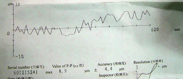
Calibration certificate that came with it, for what it's worth (don't know about Taiwanese certificated, but Chinese certificates are a waste of paper):
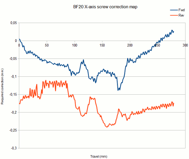
Connected the hardware:
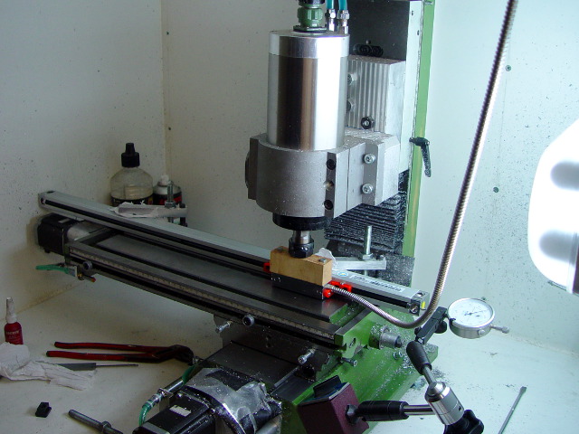
Connected the encoder output to motion.analog-in-00 and wrote a few lines of G-code to travel the entire range in 256 steps and write a compensation map using (LOG, ...).
Result. Scale is milimeters, blue is the required compensation (midpoint between fwd/rev corrections), red is compensated:
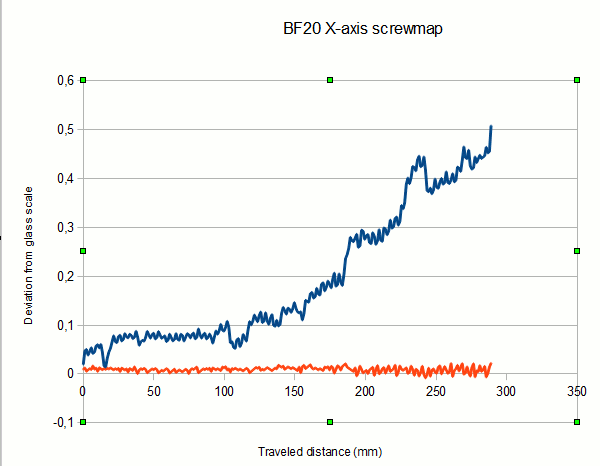
I find the blue graph hard to believe. Will have to do some extra checking with analog dial indicators.
Also did a quick stab at closing the loop, but no real success there yet. And if the compensated curve looks the same within a few weeks as it does now, there is no need to perform extra calibration either.
Please Log in or Create an account to join the conversation.
- DaBit
- Offline
- Platinum Member
-
- Posts: 446
- Thank you received: 35
New compensation map:
Oh my, that's a terrible amount of backlash

It used to be less. I suspect the ballnut mounting method used on the BF20/G0704. Backlash on the X axis is bugging me ever since I bought the machine. Thought it was the leadscrew, so i replaced that one with a ball screw and backlash went to 0,02mm. But I guess the leadscrew is not the root cause. *sigh*
At the moment I have the axis running in closed-loop using the screw map for the majority of the compensation and a PID-loop to cancel the residual error. It runs a little rough and I get an occasional following error, but it seems to work.
Please Log in or Create an account to join the conversation.
- andypugh
-
- Offline
- Moderator
-
- Posts: 23485
- Thank you received: 4994
It's certainly not great. I don't know how much might be due to each of the possoble causes.Oh my, that's a terrible amount of backlash
Can you twist the bed in its guides? How much does that move things? With your new mounting you can detect anglular as well as linear backlash.
You might learn a lot from putting the DTI on the end of the ballscrew. Perhaps the screw moves in its bearings?
Please Log in or Create an account to join the conversation.
- DaBit
- Offline
- Platinum Member
-
- Posts: 446
- Thank you received: 35
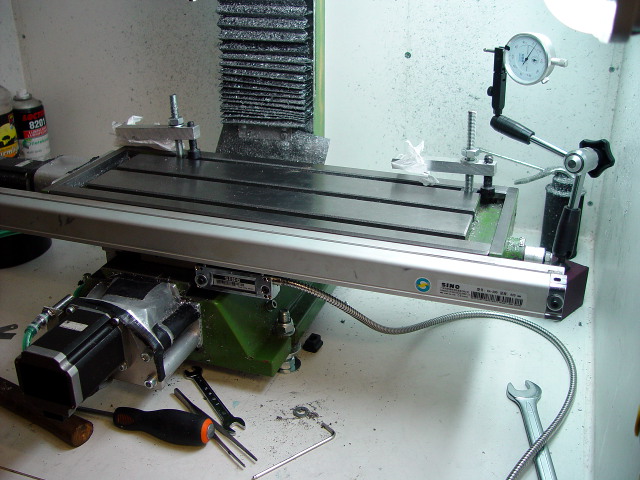
The slide moves on the base (Y-axis slop) about 0,01mm when pushing or pulling with full force. X-axis is worse; that's around 0.4mm with the table at the end of the travel (maximum extension).
I already tried lapping the ways with some grinding paste, which improved things a little. Scraping is probably the only option that yields good results.
But I won't go that route, not with this machine. I can spend a million hours tinkering with it, and then it is probably 'acceptable' or 'decent'.
You get what you pay for with these Chinese machines...
In my case I didn't buy it because I wanted a CNC mill; the CNC was added because I wanted a DRO. And a bunch of steppers + LinuxCNC provides DRO, power feed, and CNC.
Now I love CNC and LinuxCNC as well. I can't think of another system which allows me to interface a glass scale using two parallel port pins and add some arithmetic and control to the positioning loop so easily. Maybe KFLOP is close, maybe not.
Using this machine to build a better machine, and then sell it is a far better plan imho. For this I needed to know if 'inaccurate' C7 screws can be compensated enough. The answer is 'yes'. I also wanted to know if closed loop positioning using a glass scale is an option. The answer is again 'yes'. So I will include the option to mount them, but do so only if it proves to be necessary.
Please Log in or Create an account to join the conversation.