PID tuning: one vs multiple loops, gain scheduling
- DaBit
- Offline
- Platinum Member
-

- Posts: 446
- Thank you received: 35
The machine is a gantry style mill using analog torque mode servos on X- and the two Y axes/joints. In addition to the 2048-lines encoders on the servos I use 1um-resolution linear scales.
Currently the control loop is setup like this:
axis.N.motor-pos-cmd ---(position)---> scale PID ---(position)---> servo PID ---(torque)---> 7i77
Servo PID gets feedback from the rotary encoder, scale PID gets feedback from the scale.
The servo PID is the workhorse; All of the proportional/derivative gain is there, as well as FF1/FF2.
The scale PID uses I gain only. It has only has to correct a slowly rising error and has to be insensitive to jitter. It also has a limited output to prevent disaster when a scale breaks down.
Servo thread runs at 5kHz at the moment. A bit higher than required, but the PC is able to keep up so it does not hurt either.
This setup works fine, as long as motion is commanded from LinuxCNC. Then the carefully tuned FF1/FF2 feedforward does it's job and loop response is quick and accurate.
However, the response to external disturbances and small correction values (Y<->Z angle is not exactly 90.000 degrees for example; I am using a correction curve to compensate that) is not so great. A position error of, say, 0,03mm does not produce much correcting torque through P/D and the I term becomes slow also since integrating a small value just takes time.
Now, where do I go from here?
- Making P/I/D more agressive and eventually reducing FF1/FF2 does not bring much.
- I could split the servo PID in two parts: a velocity PID that outputs torque and a position PID that outputs velocity. Would that help?
- I could implement a form of gain scheduling and have 'lincurve' feed the PID gains. Use less agressive parameters (mainly I i think) at high speed and more agressive parameters at low speed or something like that. Most servo drives seem to do a switch between two or more sets of parameters depending on velocity. But what are the rules? When to change what parameter? I cannot find much literature about this.
Please Log in or Create an account to join the conversation.
- Todd Zuercher
-

- Offline
- Platinum Member
-
- Posts: 5034
- Thank you received: 1467
I also wasn't able to get that pc to run half as fast a servo thread speed, and I'm not all that pleased with its response either.
Please Log in or Create an account to join the conversation.
- DaBit
- Offline
- Platinum Member
-
- Posts: 446
- Thank you received: 35
The separate velocity loop allowed me to tune that first by connecting it to a siggen.
All in all I learned a few things:
- The velocity signal coming from the 7i77 encoder is very noisy at low speeds. Probably the 7i77 is correct; with low load inertia there is a constant jitter. But this is a problem as P and D couple the noise to the output.
- Filtering the velocity with a biquad before feeding it to PID to remove high frequency noise worsens things. The loop cannot handle the extra delay in the velocity signal unless the coefficients are set to a really slow response. This even happens when I put the cutoff at 500Hz.
- Filtering the torque output to the drive is even worse. Anything below 1500Hz and it is impossible to get rid of huge under/overshoots. This implies that the absolute minimum servo thread frequency for this axis would be 3kHz.
- By far the best tracking and lowest overshoot is obtained when the loop is tuned agressive enough to cause a slighty vibrating motor shaft. The noise is irritating though.
I also did a rough tune of the position loop. Tracking error is still a lot higher than the old single-PID situation but stiffness seems to have improved. With the whining motor, that is.
All in all the improvements are marginal so far. But to be honest I have spent countless hours tuning the single-PID loop to it's current state.
One more question: I would like to try an even higher frequency for the velocity PID. I suppose I can setup a base thread, enable 'base_thread_fp=1' when loading motmod, and move the do-pid-calcs function to the base thread. Then I would also need to move hm2_5i25.0.read, hm2_5i25.0.write (and possibly hm2_5i25.0.pet_watchdog) to the base thread. The advantage would be that the rest of LinuxCNC can run at a more normal servo rate; with 5kHz the UI already becomes sluggish from time to time.
But I suppose that the smart serial I/O used to read/write the GPIO imposes an upper limit.
Does anyone know that limit?
Please Log in or Create an account to join the conversation.
- PCW
-

- Offline
- Moderator
-

- Posts: 19117
- Thank you received: 5280
Velocity is always noisy at low speeds, with low resolution encoders there just is not much for the velocity
estimation to work with. Because of this issue, newer drives have gone to high resolution serial encoders to improve velocity estimation.
Buzzing when idle as also hard to eliminate at high gains because even a single encoder count generates a significant output
(put another way, if your error band is within say +-16 counts you only have 5 bits of control resolution in the area of interest)
Early Fanuc drives had 2000 to 3000 line (8000 to 12000 CPT) quadrature encoders then have progressed to
64K CPT, 1M CPT and currently use 16M CPT encoders to avoid this crunchyness at low speeds.
The 7I77 output filtering has a ~2.2 KHz bandwidth so going to much higher sample rates will not help the
loop bandwidth much. The sserial I/O is probably limited to somewhere around 6-8 KHz at the standard Baud rate.
The hardware and SSLBP allow 10 Mbps instead of the default 2.5 Mbps. 10 Mbps would probably get you to
12 KHz or so but requires changing the firmware default baud rate and setting the 7I77s EEPROM baud rate index.
I can build a 7I77 with perhaps 5 KHz analog output bandwidth at the expense of somewhat higher output ripple (at 48 KHz)
It might be worth the experiment. If you want to experiment, I could also send you a proto/test 7I65 to try. This would have the
advantage or running up to 20 KHz or so if the host can do it
I have also considered adding a velocity control unit to HostMot2 which runs the velocity loop independently of linuxcnc
This would use the same 32 bit embedded processor we currently use with our resolver interface.
Please Log in or Create an account to join the conversation.
- DaBit
- Offline
- Platinum Member
-
- Posts: 446
- Thank you received: 35
A couple of things:
Velocity is always noisy at low speeds, with low resolution encoders there just is not much for the velocity
estimation to work with.
Buzzing when idle as also hard to eliminate at high gains because even a single encoder count generates a significant output
Yes, I figured that out also. Unfortunately I have these drives and motors, and they will have to do.
It seems that most (all?) servo drives reduce PID/PIV gains once the motor is close to it's target and increase filtering on the velocity signal. See page 18 for example . This probably answers my gain scheduling question too.
And then we have the problem of mechanical issues: www.ormec.com/Portals/0/files/Services/A...s/Couplingservos.pdf
And the possibility of using white noise injection to figure out those resonances and notch filters to suppress them: www.controleng.com/single-article/use-in...90d00db92f67816.html
Things are definitely not as easy as they seem. In hindsight I should have used larger diameter ballscrews and wider belts instead of just minimizing inertia while keeping deformation due to the acting forces acceptable. Oh well, figuring out what you really should have done months ago is routine for an engineer.
")
The 7I77 output filtering has a ~2.2 KHz bandwidth so going to much higher sample rates will not help the
loop bandwidth much.
..
I can build a 7I77 with perhaps 5 KHz analog output bandwidth at the expense of somewhat higher output ripple (at 48 KHz)
It might be worth the experiment.
If you could provide (part of) an assembly drawing and instructions in the form of a 'R61 was 10k, should become 4k7' list or schematic with new values added I can do that myself. I am experienced in manually reworking/assembling PCB's with components down to 0402 and 0,25mm pitch and have access to the tools needed to do so (I happen to design electronics for a living). Saves you a lot of time.
Since the 750W motor drive uses only 7,5kHz PWM (and run their current loops at the same frequency I assume) and the 400W motors only 12,5kHz PWM, 5kHz should do.
If you want to experiment, I could also send you a proto/test 7I65 to try. This would have the
advantage or running up to 20 KHz or so if the host can do it
I currently have both connectors of the 6i25 in use (one 7i77, one extra encoder channels and stepgens on a custom breakout), but it seems that only 10 6i25 I/O's are needed for the 7i65 analog functions. I have those available, making the cable is no problem either, and when I tried to build a customised FPGA image a while ago it loaded.
I love test hardware but if you send it to me I would like to actually really do something with it in exchange. So my suggestion would be that if a modified 7i77 improves things it would be worth the effort to try the 7i65.
I have also considered adding a velocity control unit to HostMot2 which runs the velocity loop independently of linuxcnc
This would use the same 32 bit embedded processor we currently use with our resolver interface.
If running hostmot2 and LinuxCNC RT components such as PID, biquad, limit3, idb, etc. in an FP-enabled base thread works I would prefer that. IMHO the real beauty of LinuxCNC is that you can setup your stuff any way you want, if I want to experiment with exotic control strategies such as sliding mode control I write a few lines of C code and put them through 'comp, and being able to visualise through halshow/halscope is valueable too.
Normally a 30-50kHz base thread is no problem. FP adds quite a bit of state save/restore overhead, so let's say (very wild guess...) we can do half of non-FP base thread frequency. That's still 15-25kHz, which should cover 99% of all control loops except the the current loops.
Please Log in or Create an account to join the conversation.
- PCW
-
- Offline
- Moderator
-
- Posts: 19117
- Thank you received: 5280
Has the analog channel 0 schematic and an assy chart
(all other channels have identical component placements)
Please Log in or Create an account to join the conversation.
- DaBit
- Offline
- Platinum Member
-
- Posts: 446
- Thank you received: 35
BTW: to do a decent analysis I created quick&dirty 'whitenoise' and 'linear sine sweep' components. Together with sampler/halsampler and octave they should allow me to create a few bodeplots of the servo system, notch out resonant peaks that may prevent more agressive tuning and gain a bit of insight.
Didn't run it on the system yet, but in case anybody is interested:
whitenoise.comp:
component whitenoise "Generate white noise";
pin in float amplitude=1.0 "Amplitude of the white noise";
pin out float out "white noise output";
function _;
description """
White noise generator, can be used to find mechanical system resonances
""";
license "GPL"; // indicates GPL v2 or later
author "DaBit (dabitATicecoldcomputingDOTcom)";
;;

#include <rtapi_math.h>

// ran2 random number generator from 'numerical recipes in C'

#define IM1 2147483563
#define IM2 2147483399
#define AM (1.0/IM1)
#define IMM1 (IM1-1)
#define IA1 40014
#define IA2 40692
#define IQ1 53668
#define IQ2 52774
#define IR1 12211
#define IR2 3791
#define NTAB 32
#define NDIV (1+IMM1/NTAB)
#define EPS 1.e-14
#define RNMX (1.0-EPS)

static int randx=0;

double ran2(int *idum)
{
    int j;
    int k;
    static int idum2 = 123456789;
    static int iy = 0;
    static int iv[NTAB];
    double temp;

    if (*idum <= 0) {		// *idum < 0 ==> initialize
	if (-(*idum) < 1)
	    *idum = 1;
	else
	    *idum = -(*idum);
	idum2 = (*idum);

	for (j = NTAB+7; j >= 0; j--) {
	    k = (*idum)/IQ1;
	    *idum = IA1*(*idum-k*IQ1) - k*IR1;
	    if (*idum < 0) *idum += IM1;
	    if (j < NTAB) iv[j] = *idum;
	}
	iy = iv[0];
    }
    k = (*idum)/IQ1;
    *idum = IA1*(*idum-k*IQ1) - k*IR1;
    if (*idum < 0) *idum += IM1;

    k = idum2/IQ2;
    idum2 = IA2*(idum2-k*IQ2)-k*IR2;
    if (idum2 < 0) idum2 += IM2;

    j = iy/NDIV;
    iy = iv[j] - idum2;
    iv[j] = *idum;
    if (iy < 1) iy += IMM1;

    if ((temp = AM*iy) > RNMX)
	return RNMX;
    else
	return temp;
}

double randinter(double a, double b)	/* return a random number uniformly
					   distributed between a and b */
{
    return a + (b-a)*(ran2(&randx));
}


FUNCTION(_)
{
	out = randinter(amplitude*-1.0, amplitude);
}
sinesweep.comp"
component sinesweep "Generate a linear sine sweep";
pin in float amplitude=1.0 "Amplitude of the output sine";
pin out float output "sine sweep output";
pin out float current_frequency "Current frequency";
pin io bit start "Set to 1 to start the sweep. The component will reset this pin to 0 when done";
param rw float start_freq "Start frequency";
param rw float end_freq "End frequency";
param rw float sweep_duration "Duration of the sweep in seconds";
param r float dbg_fperiod;
variable float angle;
variable float curr_freq;
variable int prev_start=0;
variable int busy=0;
function _;
description """
Linear sine sweep generator, can be used to find mechanical system resonances.
""";
license "GPL"; // indicates GPL v2 or later
author "DaBit (dabitATicecoldcomputingDOTcom)";
;;

#include <rtapi_math.h>

#define PI2 6.283185307179586476925286766559

FUNCTION(_)
{
	if (prev_start == 0 && start) {
		start = 1;
		prev_start = 1;
		busy=1;
		angle = 0.0;
		curr_freq = start_freq;
	} else {
		if (!busy) {
			prev_start=0;
			output = 0.0;
			current_frequency = 0.0;
		}
	}
	if (busy) {
		curr_freq += (((end_freq-start_freq)/sweep_duration)*fperiod);
		current_frequency = curr_freq;
		if (curr_freq > end_freq) {
			busy=0;
			start=0;
			prev_start=0;
		} else {
			angle += PI2*curr_freq*fperiod;
			output = (amplitude*sin(angle));
		}
	}
	dbg_fperiod = fperiod;
}Please Log in or Create an account to join the conversation.
- PCW
-
- Offline
- Moderator
-
- Posts: 19117
- Thank you received: 5280
Please Log in or Create an account to join the conversation.
- DaBit
- Offline
- Platinum Member
-
- Posts: 446
- Thank you received: 35
I will approximately halve the capacitor values on an unused channel (using 2n2/220p/470p 5% NP0/C0G types) which should double the bandwidth. Then I will wire two channels in parallel in HAL, which allows me to swap low BW/high BW by plugging the connector in another channel.
Please Log in or Create an account to join the conversation.
- DaBit
- Offline
- Platinum Member
-
- Posts: 446
- Thank you received: 35
Images are very raw Octave plots; I didn't even window the FFT data or bother to put labels in the plots.
White noise:

Sine sweep:
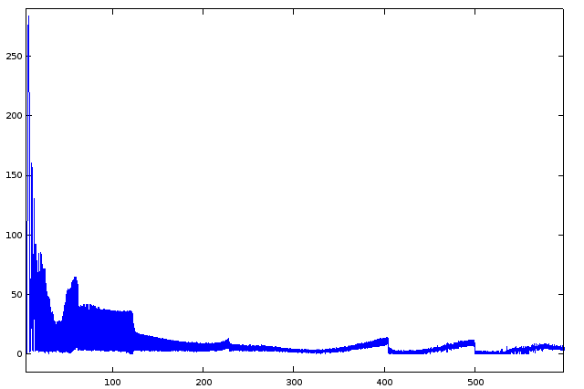
Looks useful.
Around 11Hz and 13Hz there seem to be a few peaks.
59Hz is strong, 224Hz, 400Hz en 493Hz also.
Lets add a few notch filters and see what happens...
Please Log in or Create an account to join the conversation.