PID tuning of Rexroth Ecodrive
- hardware_crash
-
 Topic Author
- Offline
- Premium Member
-

Less
More
- Posts: 80
- Thank you received: 1
04 Nov 2014 21:41 - 04 Nov 2014 21:52 #52768
by hardware_crash
PID tuning of Rexroth Ecodrive was created by hardware_crash
He guys,
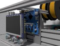
I have set up my cnc machine with Rexroth Indramat Ecodrive units with +/-10 V inputs.
I have connected the drives with a shielded cable to the 7i33TA which is mounted in an aluminum case .
The shielding of the cable is connected one time with the aluminum case which is connected to ground and on the other side its connected with the drive case which is also connected to ground.
The Ecodrive unit is an closed loop drive by itself with an emulated encoder output which Im using to get the encoder position back to linuxcnc. I set the encoder count per turn output of the Ecodrive to 6000 lines per turn as its possible to use any value for the encoder emulation output.
Now im planing on how to get these drives to work fine for me .
I tried to use the drives in velocity mode but with bad results as i think.
My settings are:
but i cant decrease the following error of this axis any better :
I made a run from 0 to 50mm with the max velocity of 4000mm/min
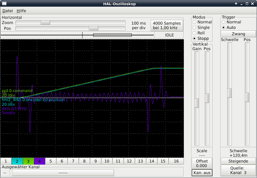
I think that the error is too large at the start and end of the motion but FF2 does not affect the hight of the spikes showing in the picture... theres also a ripple on the ferror line with a hight of 0,5m the whole time the motor is at position
What other way can I ty to make this dives work fine ? torque mode ?
The ecodrives can handle different input modes as velocity , torque and positioning control
Should i try to set the drive to torque mode ??
I have set up my cnc machine with Rexroth Indramat Ecodrive units with +/-10 V inputs.
I have connected the drives with a shielded cable to the 7i33TA which is mounted in an aluminum case .
The shielding of the cable is connected one time with the aluminum case which is connected to ground and on the other side its connected with the drive case which is also connected to ground.
The Ecodrive unit is an closed loop drive by itself with an emulated encoder output which Im using to get the encoder position back to linuxcnc. I set the encoder count per turn output of the Ecodrive to 6000 lines per turn as its possible to use any value for the encoder emulation output.
Now im planing on how to get these drives to work fine for me .
I tried to use the drives in velocity mode but with bad results as i think.
My settings are:
# PID tuning params
DEADBAND =              0.000088
P =                     10
I =                     0
D =                     1e-05
FF0 =                   0
FF1 =                   0.061
FF2 =			0.00022
BIAS =                  0
but i cant decrease the following error of this axis any better :
I made a run from 0 to 50mm with the max velocity of 4000mm/min
I think that the error is too large at the start and end of the motion but FF2 does not affect the hight of the spikes showing in the picture... theres also a ripple on the ferror line with a hight of 0,5m the whole time the motor is at position
What other way can I ty to make this dives work fine ? torque mode ?
The ecodrives can handle different input modes as velocity , torque and positioning control
Should i try to set the drive to torque mode ??
Last edit: 04 Nov 2014 21:52 by hardware_crash.
Please Log in or Create an account to join the conversation.
- BigJohnT
-

- Offline
- Administrator
-

Less
More
- Posts: 6999
- Thank you received: 1176
04 Nov 2014 22:35 #52769
by BigJohnT
Replied by BigJohnT on topic PID tuning of Rexroth Ecodrive
If I understand you correctly you have the shield conneced at both ends! This creates a current loop and will drive your signals nuts. Shielding is grounded ONLY at one end to make a drain and not a loop.
JT
JT
Please Log in or Create an account to join the conversation.
- PCW
-

- Offline
- Moderator
-

Less
More
- Posts: 18958
- Thank you received: 5236
04 Nov 2014 22:49 #52770
by PCW
Replied by PCW on topic PID tuning of Rexroth Ecodrive
Velocity mode should be easier to tune than torque mode
Is the velocity loop of the drive tuned? Thats the first step...
Also any velocity command input filtering should be turned off
Is the velocity loop of the drive tuned? Thats the first step...
Also any velocity command input filtering should be turned off
Please Log in or Create an account to join the conversation.
- hardware_crash
-
Topic Author
- Offline
- Premium Member
-
Less
More
- Posts: 80
- Thank you received: 1
05 Nov 2014 00:20 #52774
by hardware_crash
Replied by hardware_crash on topic PID tuning of Rexroth Ecodrive
@BigJohnT
Okay i also tried with shlieding on just one side but that didnt change anything ...
@PCW
The velocity lopp of the drive should be okay as the Ecodrive seem to use their own parameters for each fitting motor ..
Okay i also tried with shlieding on just one side but that didnt change anything ...
@PCW
The velocity lopp of the drive should be okay as the Ecodrive seem to use their own parameters for each fitting motor ..
Please Log in or Create an account to join the conversation.
- PCW
-
- Offline
- Moderator
-
Less
More
- Posts: 18958
- Thank you received: 5236
05 Nov 2014 00:39 - 05 Nov 2014 00:40 #52775
by PCW
Replied by PCW on topic PID tuning of Rexroth Ecodrive
Velocity loop tuning is load dependent so you must tune the drives velocity loop
(with final mechanics)
(with final mechanics)
Last edit: 05 Nov 2014 00:40 by PCW.
Please Log in or Create an account to join the conversation.
- hardware_crash
-
Topic Author
- Offline
- Premium Member
-
Less
More
- Posts: 80
- Thank you received: 1
05 Nov 2014 02:27 #52783
by hardware_crash
Replied by hardware_crash on topic PID tuning of Rexroth Ecodrive
So I tried optimizing the pid loop fo a fw hous now and cant gt better results than this :
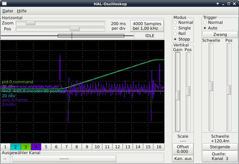

When the motor isnt in motion theres always an ferror of about 1m visible on the scope does anybody have an idea where this can come from?
The spikes while de/acceleration also dont change with my modifikations
When the motor isnt in motion theres always an ferror of about 1m visible on the scope does anybody have an idea where this can come from?
The spikes while de/acceleration also dont change with my modifikations
Please Log in or Create an account to join the conversation.
- BigJohnT
-
- Offline
- Administrator
-
Less
More
- Posts: 6999
- Thank you received: 1176
05 Nov 2014 06:38 #52787
by BigJohnT
Replied by BigJohnT on topic PID tuning of Rexroth Ecodrive
Are you using a method to tune the PID or just guessing?
gnipsel.com/linuxcnc/tuning/servo.html
Make sure ALL of your shields are only grounded on one end.
JT
gnipsel.com/linuxcnc/tuning/servo.html
Make sure ALL of your shields are only grounded on one end.
JT
Please Log in or Create an account to join the conversation.
- DaBit
- Offline
- Platinum Member
-

Less
More
- Posts: 446
- Thank you received: 35
05 Nov 2014 06:52 - 05 Nov 2014 07:15 #52788
by DaBit
Replied by DaBit on topic PID tuning of Rexroth Ecodrive
Is that following error in millimeters? So that's 2 milli-millimeters or 2 microns per division. And a micron really is not much at all.
That is not bad, or is it?
A couple of spikes at the beginning and ending of the move don't surprise me either; the LinuxCNC trajectory generator does infinite jerk (jerk=derivative of acceleration). Real motors do not do infinite jerk, the connected mechanics are not infinitely stiff and the drive electronics are not infinitely fast.
Your Igain seems to be zero, so that might explain the residual following error. If the ferror stays at 1 micron at rest I would not care too much about adding Igain.
Last edit: 05 Nov 2014 07:15 by DaBit.
Please Log in or Create an account to join the conversation.
- hardware_crash
-
Topic Author
- Offline
- Premium Member
-
Less
More
- Posts: 80
- Thank you received: 1
05 Nov 2014 21:30 - 05 Nov 2014 21:32 #52817
by hardware_crash
Replied by hardware_crash on topic PID tuning of Rexroth Ecodrive
Dear DaBit,
I now added some I gain and the ferror while motor stands still is now significant better")
I have now a ferror while no motion of about 200μ which I think is aceptable ?!
But the spikes at de/acceleration wont get any smaller
My actual settings are:

Will it be better to set a higher Encoder rate on the Ecorive unit ? Actually I set it to 6000 lines per turn ..
I also set the drive to 4000 rpm per 10V input signal... its possible to set this value to max 8000 rpm per 10V
Is this a point where I can optimize things ?
I now added some I gain and the ferror while motor stands still is now significant better
I have now a ferror while no motion of about 200μ which I think is aceptable ?!
But the spikes at de/acceleration wont get any smaller
My actual settings are:
DEADBAND =              0.000025
P =                     5
I =                     10
D =                     0.005
FF0 =                   0
FF1 =                   0.03055
FF2 =			6e-05
BIAS =                  0
Will it be better to set a higher Encoder rate on the Ecorive unit ? Actually I set it to 6000 lines per turn ..
I also set the drive to 4000 rpm per 10V input signal... its possible to set this value to max 8000 rpm per 10V
Is this a point where I can optimize things ?
Last edit: 05 Nov 2014 21:32 by hardware_crash.
Please Log in or Create an account to join the conversation.
- BigJohnT
-
- Offline
- Administrator
-
Less
More
- Posts: 6999
- Thank you received: 1176
05 Nov 2014 22:25 #52819
by BigJohnT
Replied by BigJohnT on topic PID tuning of Rexroth Ecodrive
If you look at the link I posted you will see that I and D are usually not needed for a velocity servo.
JT
JT
Please Log in or Create an account to join the conversation.
Time to create page: 0.303 seconds