PID tuning of Rexroth Ecodrive
- Todd Zuercher
-

- Offline
- Platinum Member
-

Less
More
- Posts: 5034
- Thank you received: 1467
05 Nov 2014 22:31 #52821
by Todd Zuercher
Replied by Todd Zuercher on topic PID tuning of Rexroth Ecodrive
What does it look like with FF2=0?
What is your backlash like on the axis?
A little info about the mechanics of the system? (drive type, gear reduction,...)
Also you may want to try plotting PID error instead of axis.N.error. There have been some issues (in the past) with how axis.N.error is calculated, depending on the version of LinuxCNC.
You might also need to rethink your idea of what is "good enough"
Please Log in or Create an account to join the conversation.
- DaBit
- Offline
- Platinum Member
-
Less
More
- Posts: 446
- Thank you received: 35
05 Nov 2014 23:26 - 05 Nov 2014 23:28 #52822
by DaBit
Define 'acceptable'..
If you machine is in millimeters, you are talking about real small numbers. Remember that your units are millimeters, so '1' is not a meter, it's a millimeter.
An ferror of 200u is 200 NANOmeters.... Unless the machine is a waferstepper or something to make optical lenses that is totally insignficant. Check the stiffness of the used ballscrews and nuts for example, and calculate how much force you need to deflect that 200nm...
A bit more information on what your goal is would be nice.
Then there are the peaks.
Now, the Mesa HW induces a tiny bit of delay before it outputs the correct analog voltage. The drive has to measure the analog voltage (takes time), do magic (takes time), and turn that into a current tot the motor (takes time). Then there is a motor with inductance that resists current changes, so building up the motor current to get things moving takes time.
Summary: motor torque output is a bit delayed compared to LinuxCNC command.
Thus, LinuxCNC commands the joint to start accelerating and travelling distance.
50 microseconds later: the joint has travelled a small distance, but the motor is still at standstill. That gives a ferror
100 microseconds later: the joint has travelled another small distance, but the motor is still at standstill. More ferror.
150 microseconds later: the motor has begun moving, and tried to catch up. ferror is decreasing.
200 microseconds later: Motor is there, but it travels too fast. ferror is zero
250 microseconds later: motor overshoots slightly. ferror is negative.
(Arbitrary timescale, BTW).
And so on. During braking the same happens in reverse.
This gives you a spike whenever something changes instantly. When position changes instantly, it is obvious that the motor cannot follow. When velocity changes instantly, it is also obvious that the motor cannot follow. But the same is true for acceleration, and that value changes instantly in LinuxCNC.
Summary: I consider those peaks normal, especially when they are as small as yours.
For comparison: here is one of my plots. Orange and purple traces (position_pid.error) are comparable to your traces.
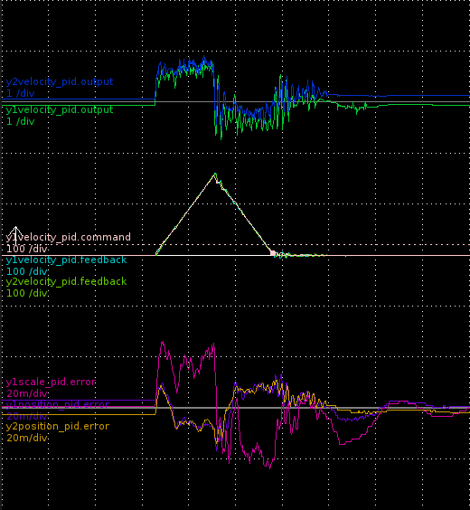
Note the scale of the errors: 20m/div. 10 times as high as your scale....
Acceleration and velocity are much higher in my plot though (3000mm/s^2, 10m/min) , and later on I managed ot approximately halve the error.
Replied by DaBit on topic PID tuning of Rexroth Ecodrive
Dear DaBit,
I now added some I gain and the ferror while motor stands still is now significant better
I have now a ferror while no motion of about 200μ which I think is aceptable ?!
But the spikes at de/acceleration wont get any smaller

Define 'acceptable'..
If you machine is in millimeters, you are talking about real small numbers. Remember that your units are millimeters, so '1' is not a meter, it's a millimeter.
An ferror of 200u is 200 NANOmeters.... Unless the machine is a waferstepper or something to make optical lenses that is totally insignficant. Check the stiffness of the used ballscrews and nuts for example, and calculate how much force you need to deflect that 200nm...
A bit more information on what your goal is would be nice.
Then there are the peaks.
Now, the Mesa HW induces a tiny bit of delay before it outputs the correct analog voltage. The drive has to measure the analog voltage (takes time), do magic (takes time), and turn that into a current tot the motor (takes time). Then there is a motor with inductance that resists current changes, so building up the motor current to get things moving takes time.
Summary: motor torque output is a bit delayed compared to LinuxCNC command.
Thus, LinuxCNC commands the joint to start accelerating and travelling distance.
50 microseconds later: the joint has travelled a small distance, but the motor is still at standstill. That gives a ferror
100 microseconds later: the joint has travelled another small distance, but the motor is still at standstill. More ferror.
150 microseconds later: the motor has begun moving, and tried to catch up. ferror is decreasing.
200 microseconds later: Motor is there, but it travels too fast. ferror is zero
250 microseconds later: motor overshoots slightly. ferror is negative.
(Arbitrary timescale, BTW).
And so on. During braking the same happens in reverse.
This gives you a spike whenever something changes instantly. When position changes instantly, it is obvious that the motor cannot follow. When velocity changes instantly, it is also obvious that the motor cannot follow. But the same is true for acceleration, and that value changes instantly in LinuxCNC.
Summary: I consider those peaks normal, especially when they are as small as yours.
For comparison: here is one of my plots. Orange and purple traces (position_pid.error) are comparable to your traces.
Note the scale of the errors: 20m/div. 10 times as high as your scale....
Acceleration and velocity are much higher in my plot though (3000mm/s^2, 10m/min) , and later on I managed ot approximately halve the error.
Last edit: 05 Nov 2014 23:28 by DaBit.
Please Log in or Create an account to join the conversation.
- hardware_crash
-
 Topic Author
- Offline
- Premium Member
-

Less
More
- Posts: 80
- Thank you received: 1
06 Nov 2014 03:07 - 06 Nov 2014 03:14 #52831
by hardware_crash
Replied by hardware_crash on topic PID tuning of Rexroth Ecodrive
Hey guys,
@BigJohnT
I know that D and I are not necessary for velocity drives but adding the I value changed my ferror while the motor stands still from about 2milli to about 200μ !
@Todd
When I change FF2 to 0 the ferror at de/acceleration rises to about 20m !
The spindles I use are 25mm diameter and 5mm per turn pitch
The motors are permanent magnet synchron servos which are directly mounted to the spindles
I will try reading the pid error tommorow and see if theres a difference to ferror.
@DaBit
At first thank you for that great explanation !!
yes my machine is set to millimeters.
your plots really are comparable to mine")
poorly the ferror is 200u not nano") So the ferror while no motion should be 0.0002 mm is that correct ?
So the ferror while no motion should be 0.0002 mm is that correct ?
But the 200 micro meters your talking about are just when the axis is already in motion , i would like to know if the spikes at de/acceleration phase which are nearly 10m high would be noticiable in my milling works or if they can anyway impar the results of the machined part ?
My velocity for this axis was about 4000mm/min according linuxcnc ... I think this would be enough for my Rapid or not ?
@BigJohnT
I know that D and I are not necessary for velocity drives but adding the I value changed my ferror while the motor stands still from about 2milli to about 200μ !
@Todd
When I change FF2 to 0 the ferror at de/acceleration rises to about 20m !
The spindles I use are 25mm diameter and 5mm per turn pitch
The motors are permanent magnet synchron servos which are directly mounted to the spindles
I will try reading the pid error tommorow and see if theres a difference to ferror.
@DaBit
At first thank you for that great explanation !!
yes my machine is set to millimeters.
your plots really are comparable to mine
poorly the ferror is 200u not nano
So the ferror while no motion should be 0.0002 mm is that correct ?But the 200 micro meters your talking about are just when the axis is already in motion , i would like to know if the spikes at de/acceleration phase which are nearly 10m high would be noticiable in my milling works or if they can anyway impar the results of the machined part ?
My velocity for this axis was about 4000mm/min according linuxcnc ... I think this would be enough for my Rapid or not ?
Last edit: 06 Nov 2014 03:14 by hardware_crash.
Please Log in or Create an account to join the conversation.
- DaBit
- Offline
- Platinum Member
-
Less
More
- Posts: 446
- Thank you received: 35
06 Nov 2014 03:29 #52833
by DaBit
Well, everybody has a different opinion, but I think a little D can have a good effect. It stabilises a larger P and it gives a more forceful signal to the drive when error changes rapidly. The drive in turn increases motor current to fullfill the demand, speeding up the response.
And those 'wobbles' int he ferror graph is probably the pitch of the screw? You might want to check how straight they are.
Depends on how accurate you are making parts. If that is 'the normal stuff' I would not worry too much about that; it is still far below 0,01mm (which is 10m in halscope). Your endmill bends more if you load it.
If you think that is speedy enough, it is. If you think it is too slow, it is too slow. It also depends on work envelope and what you are used to.
My machine is set up for 18 meters/minute rapids with a bit more than 500x600mm work envelope, but that still scares me. If I had a very large wood router 18m/min would probably feel slow.
Replied by DaBit on topic PID tuning of Rexroth Ecodrive
I know that D and I are not necessary for velocity drives but adding the I value changed my ferror while the motor stands still from about 2milli to about 200μ !
Well, everybody has a different opinion, but I think a little D can have a good effect. It stabilises a larger P and it gives a more forceful signal to the drive when error changes rapidly. The drive in turn increases motor current to fullfill the demand, speeding up the response.
The spindles I use are 25mm diameter and 5mm per turn pitch
And those 'wobbles' int he ferror graph is probably the pitch of the screw? You might want to check how straight they are.
But the 200 nano meters your talking about are just when the axis is already in motion , i would like to know if the spikes at de/acceleration phase would be noticiable in my milling works or if they can anyway impar the results of the machined part ?
Depends on how accurate you are making parts. If that is 'the normal stuff' I would not worry too much about that; it is still far below 0,01mm (which is 10m in halscope). Your endmill bends more if you load it.
My velocity for this axis was about 4000mm/min according linuxcnc ... I think this would be enough for my Rapid or not ?
If you think that is speedy enough, it is. If you think it is too slow, it is too slow. It also depends on work envelope and what you are used to.
My machine is set up for 18 meters/minute rapids with a bit more than 500x600mm work envelope, but that still scares me. If I had a very large wood router 18m/min would probably feel slow.
Please Log in or Create an account to join the conversation.
- Todd Zuercher
-
- Offline
- Platinum Member
-
Less
More
- Posts: 5034
- Thank you received: 1467
06 Nov 2014 03:59 - 06 Nov 2014 04:02 #52834
by Todd Zuercher
Replied by Todd Zuercher on topic PID tuning of Rexroth Ecodrive
It is all relative, I work with large wood routers. We have several machines that rapid over 60m/min, with cutting feeds from 2-16m/min (depending on what your cutting and with what tooling). Those machines are scarey to stand beside.
Quibbling about errors that small on a wood working machine is nonsense, I don't have any real experience with a metal working machine.
The error at rapid feed rates are mostly meaningless anyway. What matters is the error you can maintain at your desired cutting feed.
Quibbling about errors that small on a wood working machine is nonsense, I don't have any real experience with a metal working machine.
The error at rapid feed rates are mostly meaningless anyway. What matters is the error you can maintain at your desired cutting feed.
Last edit: 06 Nov 2014 04:02 by Todd Zuercher.
Please Log in or Create an account to join the conversation.
Time to create page: 0.106 seconds