How to map a ball screw?
- andypugh
-

- Away
- Moderator
-

Less
More
- Posts: 19871
- Thank you received: 4640
30 Jan 2020 08:58 #156152
by andypugh
Do you mean too fine (and encoder counts are too fast to monitor?) or are your units wrong?
Replied by andypugh on topic How to map a ball screw?
I have a lathe with both rotary encoders and linear glass scales. Both are physically connected to encoder pins and both are set to home together at the same instant (wired connection of index pulse). Only rotaries are used for position feedback. (Scales are too coarse at 0.005um).
Do you mean too fine (and encoder counts are too fast to monitor?) or are your units wrong?
Please Log in or Create an account to join the conversation.
- Nitram
-
- Offline
- Elite Member
-

Less
More
- Posts: 210
- Thank you received: 15
02 Feb 2020 17:42 #156393
by Nitram
Replied by Nitram on topic How to map a ball screw?
The units and scaling on both rotary and linear encoders are fine.
My original intention was to have dual PID loops, using the rotaries for velocity and the linears for position. This has proved to be difficult because the linear scales are too coarse at .005um and there is positional hunting and secondly with the 7i76e driving the AC servo drives via pulse and direction rather than purist velocity it is proving difficult.
So, given the scales are in situ anyway I had thought to map the C7 ballscrews with reference to the scales and thus bring in the accuracy advantages in a pseudo way to the rotary encoders.
The question therefore being whether anyone has written the G Code necessary to map the ballscrew and write the results to a file as described above and could possibly share the template.
Cheers
Marty.
Please Log in or Create an account to join the conversation.
- rodw
-

- Offline
- Platinum Member
-

Less
More
- Posts: 11975
- Thank you received: 4080
03 Feb 2020 03:58 #156416
by rodw
You could use halsampler and sampler to log positions in real time. Then import the data into a spreadsheet to do regression analysis etc.
I logged 16000 samples this way and it was pretty cool once it was summarized.
Sampler really needs a command line switch to output in CSV format though!
Replied by rodw on topic How to map a ball screw?
I think you can only have 256 points per axis.
You could use halsampler and sampler to log positions in real time. Then import the data into a spreadsheet to do regression analysis etc.
I logged 16000 samples this way and it was pretty cool once it was summarized.
Sampler really needs a command line switch to output in CSV format though!
Please Log in or Create an account to join the conversation.
- Nitram
-
- Offline
- Elite Member
-
Less
More
- Posts: 210
- Thank you received: 15
03 Feb 2020 07:37 - 03 Feb 2020 07:43 #156425
by Nitram
Replied by Nitram on topic How to map a ball screw?
Thanks Rod.
It would be interesting to do that sort of analysis (possibly ending up with a linear R2 confidence interval for the C7 screw) but for now am more looking for any previous G code which will log those positions to file in the way Andy described:
You should be able to log with LinuxCNC.
See section 16:
linuxcnc.org/docs/2.7/html/gcode/overview.html#gcode:comments
To get the scale position in to G-code use one of the "analog inputs"
linuxcnc.org/docs/2.7/html/gcode/m-code.html#mcode:m66
LOGOPEN, and LOG, (section 16) is the way to go.
(LOG, #<_X> : #5399)
Should do what you want.
Last edit: 03 Feb 2020 07:43 by Nitram.
Please Log in or Create an account to join the conversation.
- Nitram
-
- Offline
- Elite Member
-
Less
More
- Posts: 210
- Thank you received: 15
19 Feb 2020 05:42 - 19 Feb 2020 06:01 #157812
by Nitram
Replied by Nitram on topic How to map a ball screw?
Hello.
I just wanted to provide feedback to users regarding the ballscrew mapping I have done.
My lathe has C7 rolled ballscrews and by the process of ballscrew mapping and creating a compensation file, I think I have a achieved a significant improvement in linearity and accuracy.
One thing to note, the reference measuring device for the ballscrews are permanently mounted glass scales which read the axis position directly i.e. reading head mounted to the movable axis itself, scale mounted on the machine. That said, the results can only be as good as the resolution and linear accuracy of the scales themselves, but I think it is reasonable to assume that they are far better than the C7 ballscrews and backlash free.
Firstly, the G Code to write positions to a file. Note that the machine derived X axis position comes from the machine's calculated position and in this case, the glass scale position comes from Analogue input 00. The file created is saved into the config folder. I have opened the file using the LOGAPPEND command, and placed keywords at the start ("forwards") when the axis is moving int he positive direction and "reverse" to differentiate for the compensation file. Using LOGAPPEND, the G code can be run several times and glass scale position averaged for better results as each sucessive run will be appended onto the end of the existing data in the file, with the keywords enabling the user to identify where each new data set starts and where the axis reverses itself for the return run.
Make sure the X position values are the same for the forward run and the reverse run. This will enable you to place the actual (glass scale) position alongside the nominal (machine axis) position for both forward and also reverse (nullifying backlash). Divide the extreme travel of the axis by 256 to determine the increment of successive position. The comp file can only handle 256 data points. It is best f the data points are not "in harmony" with the natural pitch of the screw as this could cause missing a latent cyclic trend in the ballscrew. In other words if you have a 5mm pitch ballscrew, do not set the increment to any round multiple of 5mm. In the example G code below, with 10mm pitch ballscrews, a sample was taken every 0.6mm.
Before running the G code, ensure that the backlash in the .ini file is set to zero.
%
G94 G90 G21
G49
G54 (**MAKE SURE G54 OFFSETS TO ZERO**)
G8 (**RADIUS MODE**)
G0 X -95.000 (RAPID TO START OF AXIS)
(LOGAPPEND,x_axis_ballscrew_map.txt)
(LOG, FORWARD)
G1 F50 X -94.400
M66 E00 L0
(LOG, #<_X> : #5399)
X -93.800
M66 E00 L0
(LOG, #<_X> : #5399)
X -93.200
M66 E00 L0
(LOG, #<_X> : #5399)
.
.
.
X 34.600
M66 E00 L0
(LOG, #<_X> : #5399)
X 35.200
M66 E00 L0
(LOG, #<_X> : #5399)
X 35.800
M66 E00 L0
(LOG, #<_X> : #5399)
X 36.400
M66 E00 L0
(LOG, #<_X> : #5399)
(LOG, REVERSE)
G1 F50 X 35.800
M66 E00 L0
(LOG, #<_X> : #5399)
X 35.200
M66 E00 L0
(LOG, #<_X> : #5399)
X 34.600
.
.
.
X -93.200
M66 E00 L0
(LOG, #<_X> : #5399)
X -93.800
M66 E00 L0
(LOG, #<_X> : #5399)
X -94.400
M66 E00 L0
(LOG, #<_X> : #5399)
(LOGCLOSE)
M30
Note how the data points are the same moving forwards and reverse.
The file written will look like this:
START
FORWARD
-94.400000:-94.560000
-93.800000:-93.945000
-93.200000:-93.325000
-92.600000:-92.710000
.
.
.
35.800000:35.745000
36.400000:36.355000
REVERSE
35.800000:35.795000
35.200000:35.210000
.
.
.
-92.600000:-92.660000
-93.200000:-93.280000
-93.800000:-93.900000
-94.400000:-94.525000
Note that this is where the keywords (start/forwards/reverse) are important, so you can decipher the data. The first part of the file sampled the data points forwards, the second part of the file (after the reverse keyword) sampled the same data points with the axis running in reverse.
Excel is your friend here to now construct the comp file. Note that sometimes excel/word/other programs will put latent unwanted characters into a file. These may have to be replaced with the find and replace function (eg. in word the hidden "line end" character may have to be copied into the "find and replace" function of word, replace it with nothing and thus be deleted from the file. Another good way is to copy from Word into a pure text file, which do not usually have such latent characters).
You will need to create the comp file with the following format:
Nominal position <space> actual forward position <space> actual reverse position
Noting that what we have measured directly from the glass scales IS the actual forward and actual reverse position listed alongside the nominal position. Thus it should be pretty straight forward to copy and paste the three data columns alongside each other to make up the comp file.
Name the comp file anything you wish. In my case I chose the suggested and unexciting x_comp.comp
Save the file into your config folder.
Adjust your .ini file to reflect the inclusion of a comp file for that axis
e.g.
COMP_FILE = file.extension in my case x_comp.comp
COMP_FILE_TYPE = 0 defines the type of comp file, in this case per the "nominal forward reverse" syntax (as mentioned above)
Remembering to "comment out" the backlash settings with the # symbol... # BACKLASH = <whatever your setting is>.
Both before and after this process, I graphed the results. The graphs are attached and are best viewed as "wide" as possible because they are rather "long" in ratio to their height.
In the "before comp" graph, one can see a gradient in the linear line of best fit. This indicates that according to the glass scales the ballscrew has a general trend of shortening up. Further, this is reflected both in the forwards (blue) measurements and the reverse (orange) measurements. Additionally, one can see that approx. 5mm intervals there is a cyclic peak/trough. Remember this is a 10mm pitch ballscrew so this is not surprising and speaks to the fact that data samples should _not_ be a multiple of the pitch to help identify these cyclic trends. Also note the difference between the forward and reverse lines at the same nominal data point. The difference being backlash.
Refer now to the "after comp" graph. This is the G code sampling program run after the installation of the comp file. Note that the vertical axis divisions are much finer than on the before comp graph so don't let that fool you. One can clearly see that the lines of best fit are now MUCH more linear, meaning that the effect of the ballscrew "shortening up" has been removed, and secondly, one can see that the average of the two lines (forwards and reverse) are largely co-linear, meaning backlash has been largely removed along the entire travel. On average, actual position deviation from nominal has been reduced to being within .005mm at the vast majority of data points along the axis length.
Whilst this is a fairly long winded post, the actual doing of this procedure is only about 2 hours (subject to how fast you run the feedrate in the G code test). I hope it serves to illustrate the power and flexibility of a comp file and Linuxcnc in general. Furthermore, I think that it has improved the accuracy of the C7 rolled ballscrews in my lathe immensely!
Cheers,
Marty.
Last edit: 19 Feb 2020 06:01 by Nitram.
The following user(s) said Thank You: Mike_Eitel, andypugh, akb1212, tommylight, pommen, DrKnow65
Please Log in or Create an account to join the conversation.
- mighty_mick
-

- Offline
- Junior Member
-

Less
More
- Posts: 37
- Thank you received: 5
12 Mar 2024 08:09 #295722
by mighty_mick
Replied by mighty_mick on topic How to map a ball screw?
Hey Nitram. I want to ask you some questions about compensation.
First of all, the compensation file is structured like machine coordinate, forward position, reverse position. When talking about negative limit, for example let my negative limit be 0. I can not go to this position in forward way. Same as this, let my positive limit be 40. I can not go to this positive limit position in reverse way. I am wondering about ho did you handle this points in your comp file?
My second question is about backlash. I was doing this process as same as you. If you don't change your procedure, it looks fine. I've got the results which is very fine. My procedure goes like this,
1. Go to negative limit
2. Go to 1mm forward.
3. The rest goes like yours
The reason that i start from 1mm forward of negative limit is i can not go to negative limit in forward way, so i can not fill that column in my compensation file. As same as negative limit, i am also implementing this behavior to my positive limit. So my compensation file looks like this:
1 .. ..
2 .. ..
.....
39 ... ..
After implementing compensation in the system, the results are fine like i said. But when i do some movement like going forward from a point and returning to that point(the point is any point between positive and negative limit), i am not able to see exact same point. Some difference exists, and i think it is about backlash. It looks like backlash still exists in system.
I am really wondering about this, have you tested your system like mine? Are you getting same results like me? For me, i might understand compensation file's purpose wrong. It is not fixing backlash in little steps. It fixes it in whole path. I mean going to 0 from 40 then going to 40 from zero. What is your recommendations or ideas?
Thank you.
Please Log in or Create an account to join the conversation.
- andypugh
-
- Away
- Moderator
-
Less
More
- Posts: 19871
- Thank you received: 4640
12 Mar 2024 12:56 #295739
by andypugh
Replied by andypugh on topic How to map a ball screw?
There is a format for the compensation file with offsets in both directions, which can attempt to compensate for backlash.
But backlash can never be properly compensated for unless the cutting forces are always in the same direction.
But backlash can never be properly compensated for unless the cutting forces are always in the same direction.
Please Log in or Create an account to join the conversation.
- Mecanix
- Offline
- Platinum Member
-
Less
More
- Posts: 447
- Thank you received: 227
12 Mar 2024 14:10 - 12 Mar 2024 14:20 #295743
by Mecanix
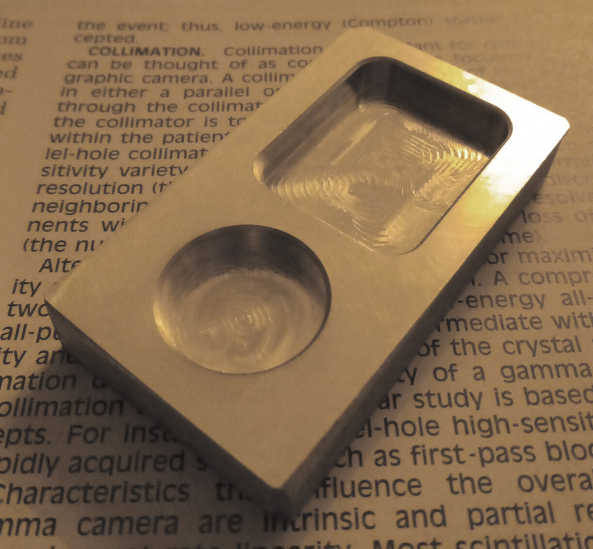
Andy, grateful if you could expand on this assumption. As per experience or theoretically? Reason I ask is because I run *.comp type 1 on all axis and getting near industrial accuracy on a low-grade XYZ stepping driven milling machine with X0.054, Y0.065, Z0.071 backlash. Test part attached, features validated on the CMM at the company, certificate output = 0.004mm (max). Further down is a 20pts back & forth motion validation from a 1um calibrated glass.
Could the difference be that the compensation was acquired 255 times using a zigzag pattern? e.g. 2, 0, 4, 2, 6, 4, 8, 6, 10, 8.... ....
Replied by Mecanix on topic How to map a ball screw?
But backlash can never be properly compensated for unless the cutting forces are always in the same direction.
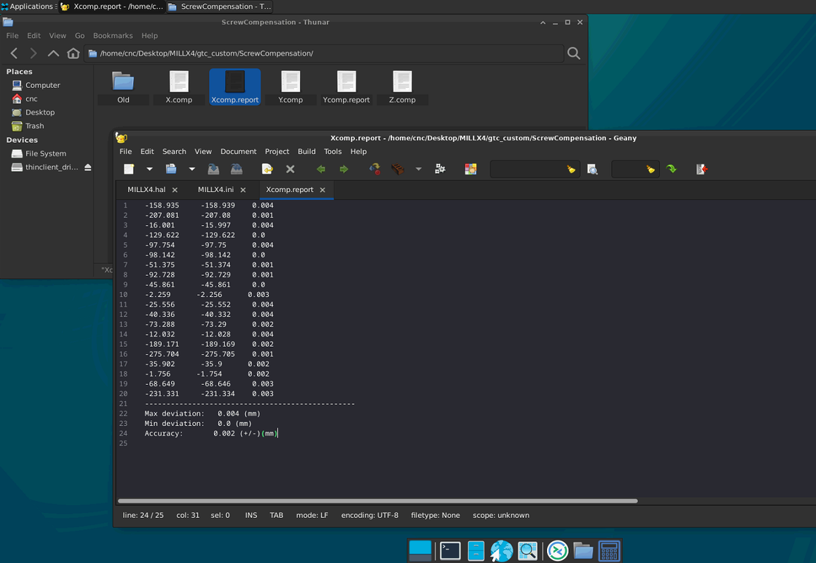
Andy, grateful if you could expand on this assumption. As per experience or theoretically? Reason I ask is because I run *.comp type 1 on all axis and getting near industrial accuracy on a low-grade XYZ stepping driven milling machine with X0.054, Y0.065, Z0.071 backlash. Test part attached, features validated on the CMM at the company, certificate output = 0.004mm (max). Further down is a 20pts back & forth motion validation from a 1um calibrated glass.
Could the difference be that the compensation was acquired 255 times using a zigzag pattern? e.g. 2, 0, 4, 2, 6, 4, 8, 6, 10, 8.... ....
Last edit: 12 Mar 2024 14:20 by Mecanix.
Please Log in or Create an account to join the conversation.
- andypugh
-
- Away
- Moderator
-
Less
More
- Posts: 19871
- Thank you received: 4640
12 Mar 2024 15:48 #295758
by andypugh
Replied by andypugh on topic How to map a ball screw?
Conventional or climb milling? I would expect the backlash part of compensation to fail completely when climb milling. Though it would depend on table friction and the relative to the cutting forces.
Please Log in or Create an account to join the conversation.
- Mecanix
- Offline
- Platinum Member
-
Less
More
- Posts: 447
- Thank you received: 227
12 Mar 2024 17:35 - 12 Mar 2024 17:37 #295766
by Mecanix
Replied by Mecanix on topic How to map a ball screw?
Interesting. Compensation for X & Y was measured with the table preloaded. As in, having the usual and heavy fixturing/clamping gears (+10%) that it normally sees during production. That solved the non-linear backlash error part.
In my case anyway, and regardless of the force/direction/cutting method, that backlash is applied when motion reverse and translates snugged. Confirmed with the parts I've made so far. Also confirmed with "joint.0.backlash-corr".
Thinking about it though, you're right, might be a whole different story for those feather light machines, particularly those on linear rails...
Last edit: 12 Mar 2024 17:37 by Mecanix.
Please Log in or Create an account to join the conversation.
Time to create page: 0.140 seconds