Include rotation from A in G0
- anpoit00
- Offline
- New Member
-

Less
More
- Posts: 11
- Thank you received: 0
06 Dec 2019 13:26 #152154
by anpoit00
Include rotation from A in G0 was created by anpoit00
Hello,
I am trying to create a small cutting machine with 3 Axis - X Y linear axis and "A" rotate axis. I changed trivial kinematics module, calculate derivative of the way and calculate angle wit atan2 function. It works good but if the machine is moving with G0 i would like to set an angle of the target position (start angle of the next G1). Do I have to make changing in planner routine for the "look ahead"?
Greate thanks
Please Log in or Create an account to join the conversation.
- andypugh
-

- Offline
- Moderator
-

Less
More
- Posts: 19797
- Thank you received: 4606
06 Dec 2019 15:20 #152160
by andypugh
Replied by andypugh on topic Include rotation from A in G0
I don't really understand the question.
What is it about your machine that means you can't run it as a simple XYA config?
What is it about your machine that means you can't run it as a simple XYA config?
Please Log in or Create an account to join the conversation.
- anpoit00
- Offline
- New Member
-

Less
More
- Posts: 11
- Thank you received: 0
06 Dec 2019 16:02 #152161
by anpoit00
Replied by anpoit00 on topic Include rotation from A in G0
I have found a video with a familar system : . The cutter position have to be tangential to the curve in each point. During G0 it must be move to the start angle position from next G1 or G2 ...
Please Log in or Create an account to join the conversation.
- andypugh
-

- Offline
- Moderator
-

Less
More
- Posts: 19797
- Thank you received: 4606
06 Dec 2019 16:06 #152162
by andypugh
Replied by andypugh on topic Include rotation from A in G0
I think that Gcodetools for Inkscape can do this automatically.
Another option would be an input filter to modify the G-code.
I thought I had already done this once, but all I can find is a suggestion that it should be fairly easy.
forum.linuxcnc.org/38-general-linuxcnc-q...tion?start=10#127201
Another option would be an input filter to modify the G-code.
I thought I had already done this once, but all I can find is a suggestion that it should be fairly easy.
forum.linuxcnc.org/38-general-linuxcnc-q...tion?start=10#127201
The following user(s) said Thank You: anpoit00
Please Log in or Create an account to join the conversation.
- anpoit00
- Offline
- New Member
-

Less
More
- Posts: 11
- Thank you received: 0
06 Dec 2019 17:49 - 06 Dec 2019 17:51 #152166
by anpoit00
Replied by anpoit00 on topic Include rotation from A in G0
I doubt that it is work because unknowing angle for the next movement (for G1 yes but G2, G3 ..)
Last edit: 06 Dec 2019 17:51 by anpoit00.
Please Log in or Create an account to join the conversation.
- anpoit00
- Offline
- New Member
-

Less
More
- Posts: 11
- Thank you received: 0
06 Dec 2019 18:31 #152168
by anpoit00
Replied by anpoit00 on topic Include rotation from A in G0
Ok i found the place. May be for somebody interesting
4516 STRAIGHT_TRAVERSE(block->line_number, end_x, end_y, end_z,
AA_end, BB_end, CC_end,
u_end, v_end, w_end);
settings->current_x = end_x;
settings->current_y = end_y;
settings->current_z = end_z;
int Interp::convert_straight(int move,   //!< either G_0 or G_1
                            block_pointer block,        //!< pointer to a block of RS274 instructions
                            setup_pointer settings)     //!< pointer to machine settings
4516 STRAIGHT_TRAVERSE(block->line_number, end_x, end_y, end_z,
AA_end, BB_end, CC_end,
u_end, v_end, w_end);
settings->current_x = end_x;
settings->current_y = end_y;
settings->current_z = end_z;
Please Log in or Create an account to join the conversation.
- andypugh
-

- Offline
- Moderator
-

Less
More
- Posts: 19797
- Thank you received: 4606
06 Dec 2019 21:33 #152181
by andypugh
It isn't very hard if you run through the G-code line-by-line in an input filter.
Basically before every G1 put in a G0 to the tangent of the G1 section.
Additionally, for a G2 or G3 append an A move to the new angle.
Replied by andypugh on topic Include rotation from A in G0
I doubt that it is work because unknowing angle for the next movement (for G1 yes but G2, G3 ..)
It isn't very hard if you run through the G-code line-by-line in an input filter.
Basically before every G1 put in a G0 to the tangent of the G1 section.
Additionally, for a G2 or G3 append an A move to the new angle.
Please Log in or Create an account to join the conversation.
- Badger
-

- Offline
- Senior Member
-

Less
More
- Posts: 44
- Thank you received: 21
06 Dec 2019 21:47 #152184
by Badger
Replied by Badger on topic Include rotation from A in G0
I did a quick test with gcodetools using the tangent knife tool and it may do what you need. This is using the settings from my Rugbot which of course will be different from you machine.
Please Log in or Create an account to join the conversation.
- andypugh
-

- Offline
- Moderator
-

Less
More
- Posts: 19797
- Thank you received: 4606
07 Dec 2019 19:21 #152275
by andypugh
Replied by andypugh on topic Include rotation from A in G0
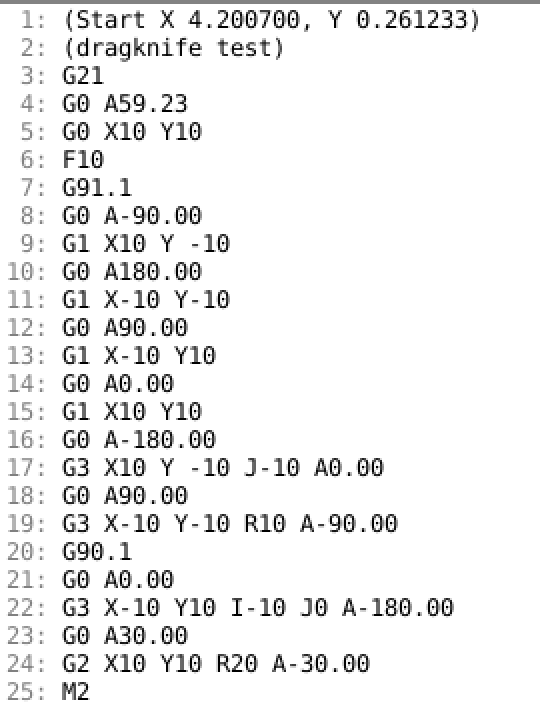
Here is a partial solution. It is an input filter that converts this input:
To this output
Which almost, but not quite, does what is needed.
The problem I am seeing is that whilst he angles of the starts and ends of arcs are correct, the tool won't necessarily turn the right direction to cut properly.
But I am going away for a week, so thought that it might be best to hand it over, in case you want to try to make the required changes.
It uses the normal atan2 convention where the +X direction is 0, +Y = 90, -X = 180/-180 and -Y = -90. Your A axis would need t change that.
A variable defined near the top allows for changing to use C for the tool rotation.
Edit the INI file [FILTER] section:
Then save this code as "dragknife", make it executable and put it in the path defined above.
(dragknife test)
G21
G0 X10 Y10
F10
G91.1
G1 X10 Y -10
G1 X-10 Y-10
G1 X-10 Y10
G1 X10 Y10
G3 X10 Y -10 J-10
G3 X-10 Y-10 R10
G90.1
G3 X-10 Y10 I-10 J0
G2 X10 Y10 R20
M2
To this output
Which almost, but not quite, does what is needed.
The problem I am seeing is that whilst he angles of the starts and ends of arcs are correct, the tool won't necessarily turn the right direction to cut properly.
But I am going away for a week, so thought that it might be best to hand it over, in case you want to try to make the required changes.
It uses the normal atan2 convention where the +X direction is 0, +Y = 90, -X = 180/-180 and -Y = -90. Your A axis would need t change that.
A variable defined near the top allows for changing to use C for the tool rotation.
Edit the INI file [FILTER] section:
[FILTER]
PROGRAM_EXTENSION = .ngc G-code
ngc = /home/andypugh/linuxcnc/dragknife
Then save this code as "dragknife", make it executable and put it in the path defined above.
#! /usr/bin/python

import re
import sys
from math import *
import linuxcnc

# Change this to alter the rotary axis letter
L = "A"

infile = sys.argv[1]

f = open(infile, 'r')

G = -99999.0
X = 0.0
Y = 0.0
oldA = -99999.0
A = 0
A2 = 0

s = linuxcnc.stat()
s.poll()
if 901 in s.gcodes:
    abs_centre = True
else:
    abs_centre = False

oldX = X = s.position[0] + s.g92_offset[0] + s.g5x_offset[0]
oldY = Y = s.position[1] + s.g92_offset[1] + s.g5x_offset[1]

print("(Start X %f, Y %f)" %(oldX, oldY))

for line in f:
    Xf = re.match(r".*X\s*([\d\.,\+\-]+)", line)
    Yf = re.match(r".*Y\s*([\d\.,\+\-]+)", line)
    If = re.match(r".*I\s*([\d\.,\+\-]+)", line)
    Jf = re.match(r".*J\s*([\d\.,\+\-]+)", line)
    Rf = re.match(r".*R\s*([\d\.,\+\-]+)", line)
    Gf = re.match(r".*G\s*([\d\.,\+\-]+)", line)

    I = 0
    J = 0
    if Xf:
        oldX = X
        X = float(Xf.group(1))
    if Yf:
        oldY = Y
        Y = float(Yf.group(1))
    if If:
        I = float(If.group(1))
    if Jf:
        J = float(Jf.group(1))
    if Rf:
        R = float(Rf.group(1))
    if Gf:
        G = float(Gf.group(1))

    if G == 90.1:
        abs_centre = True
    if G == 91.1:
        abs_centre = False

    if G == 0.0 or G == 1.0:
        A = atan2(Y - oldY, X - oldX) * 180/pi
    elif G == 2.0 or G == 3.0:
        if Rf:
            mid_x = (X + oldX) / 2.0;
            mid_y = (Y + oldY) / 2.0;
            l2 = sqrt((mid_x - X)**2 + (mid_y - Y)**2);
            if ((G == 2) and (R > 0)) or ((G == 3) and (R < 0)):
                theta = atan2((Y - oldY), (X - oldX)) - pi/2;
            else:
                theta = atan2((Y - oldY), (X - oldX)) + pi/2;
            turn2 = asin(l2 / abs(R));
            offset = abs(R) * cos(turn2);
            X0 = mid_x + (offset * cos(theta));
            Y0 = mid_y + (offset * sin(theta));
        elif abs_centre:
            X0 = I
            Y0 = J
        else:
            X0 = oldX + I
            Y0 = oldY + J

        A = atan2(Y0 - oldY, X0 - oldX) * 180/pi
        alpha = atan2(Y0 - Y, X0 - X) * 180/pi - A
        if G == 2.0:
            A = A + 90
            A2 = A + alpha
        else:
            A = A - 90
            A2 = A + alpha
    if (Xf or Yf) and G == 0.0:
        print("G0 %s%.2f" % (L, A))
        print(line),
        oldA = A
    elif (Xf or Yf) and G == 1.0:
        if oldA != A:
            print("G0 %s%.2f" % (L, A))
            if not Gf:
                line = "G1 %s" % line
        print(line),
        oldA = A
    elif (Xf or Yf) and G == 2 or G == 3:
        if oldA != A:
            print("G0 %s%.2f" % (L, A))
        line = re.sub("\n", " %s%.2f" % (L, A2), line)
        print(line)
        oldA = A2
    else:
        print(line),
Attachments:
The following user(s) said Thank You: jo_key, anpoit00, tiagounderground
Please Log in or Create an account to join the conversation.
Time to create page: 0.244 seconds

