7i76E spindle encoder - strange readouts
- fenolski
- Offline
- New Member
-

Less
More
- Posts: 12
- Thank you received: 0
28 Sep 2020 21:42 #184218
by fenolski
7i76E spindle encoder - strange readouts was created by fenolski
Hello, I read this forum often but this is my first post so I'd like to say "Hello !"
I built a spindle encoder A/B/I. I printed two 72ppr wheels and one 1ppr wheel. I used three simple optocouplers.
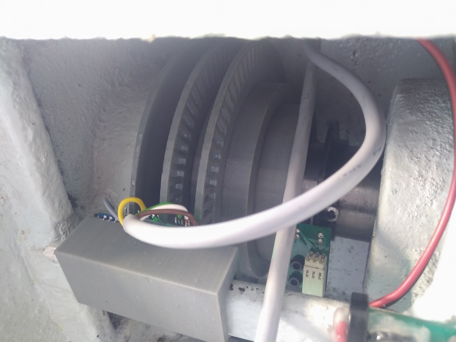

Optocouplers are connected to spindle encoder A/B/I inputs. Mesa jumpers are set to signle/TTL inputs.
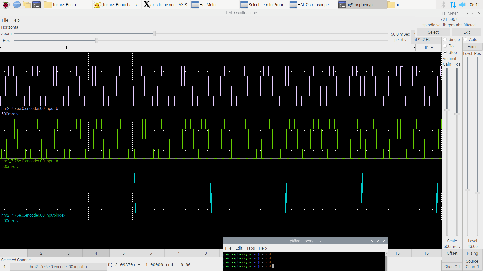
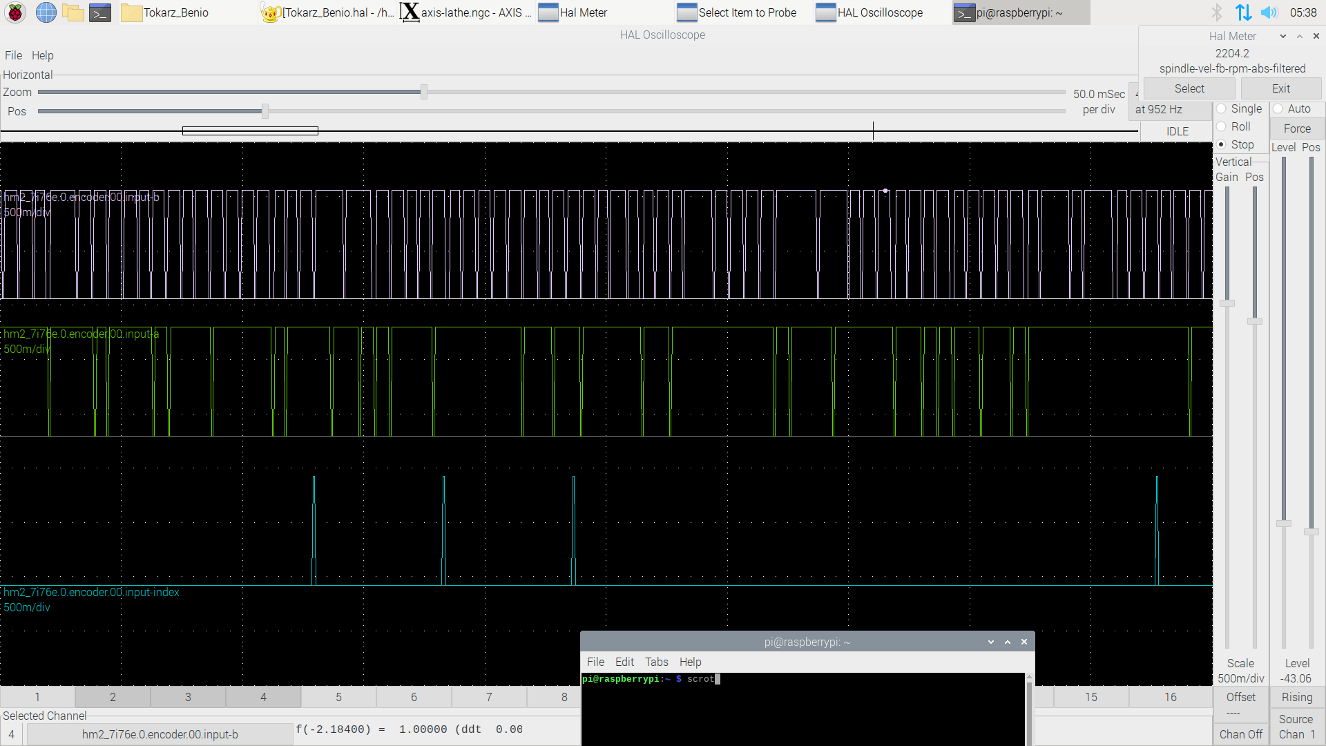
The encoder works up to 2250rpm. Over that speed Halmeter shows bad values. I used halscope at different speeds and to be honest none of the graph (even at low rpm) looks bad. Time base for all graphs are the same. The pulse should be wider at low RPMs but it doesn't look like that. Could you please help me to diagnose the problem.


I built a spindle encoder A/B/I. I printed two 72ppr wheels and one 1ppr wheel. I used three simple optocouplers.
Optocouplers are connected to spindle encoder A/B/I inputs. Mesa jumpers are set to signle/TTL inputs.
The encoder works up to 2250rpm. Over that speed Halmeter shows bad values. I used halscope at different speeds and to be honest none of the graph (even at low rpm) looks bad. Time base for all graphs are the same. The pulse should be wider at low RPMs but it doesn't look like that. Could you please help me to diagnose the problem.
Attachments:
Please Log in or Create an account to join the conversation.
- tommylight
-

- Offline
- Moderator
-

Less
More
- Posts: 21764
- Thank you received: 7438
28 Sep 2020 21:57 #184223
by tommylight
Replied by tommylight on topic 7i76E spindle encoder - strange readouts
One thing that is apparent from the pictures is that the 2 discs are in the same position in regards to their sensors, and that does not work.
For it to work properly, the disks need to have the slots set at 90 degree offset, or to put it simpler, the slot on one disc has to start at the middle of the second disc regarding their slots.
So the discs can not open or close both at the same time, and one of them can not open and second close at the same time.
Attachments:
Please Log in or Create an account to join the conversation.
- fenolski
- Offline
- New Member
-
Less
More
- Posts: 12
- Thank you received: 0
28 Sep 2020 22:09 #184224
by fenolski
Replied by fenolski on topic 7i76E spindle encoder - strange readouts
Ok, maybe the discs are not perfectly fitted but when I set mesa encoder input to A only there is the same behavior. So it looks like the 90deg fitting is not the case.
Please Log in or Create an account to join the conversation.
- OT-CNC
- Offline
- Platinum Member
-

Less
More
- Posts: 617
- Thank you received: 75
28 Sep 2020 22:38 - 28 Sep 2020 22:38 #184226
by OT-CNC
Replied by OT-CNC on topic 7i76E spindle encoder - strange readouts
You can't detect direction if they are both in phase. You need that slight shift in the second encoder wheel. I would re-print or try shifting the opto a bit, although you probably have better control over phasing if you re-print with the correct offset. I assume the disks are keyed?
Last edit: 28 Sep 2020 22:38 by OT-CNC. Reason: format
Please Log in or Create an account to join the conversation.
- fenolski
- Offline
- New Member
-
Less
More
- Posts: 12
- Thank you received: 0
28 Sep 2020 22:50 #184227
by fenolski
Replied by fenolski on topic 7i76E spindle encoder - strange readouts
I guess it is not the problem of direction. Linuxcnc detects direction of the rotation. The problem exist also in A-only (counter mode). In this mode LinuxCNC use only A signal and phase shift between A and B is, I guess, not important.
Please Log in or Create an account to join the conversation.
- OT-CNC
- Offline
- Platinum Member
-
Less
More
- Posts: 617
- Thank you received: 75
28 Sep 2020 23:12 #184229
by OT-CNC
Replied by OT-CNC on topic 7i76E spindle encoder - strange readouts
When you look at the encoder counts in hal configurator, does it count up and down?
Please Log in or Create an account to join the conversation.
- PCW
-

- Offline
- Moderator
-
Less
More
- Posts: 17996
- Thank you received: 5283
28 Sep 2020 23:21 - 28 Sep 2020 23:23 #184230
by PCW
Replied by PCW on topic 7i76E spindle encoder - strange readouts
One thing to remember is that the halscope images will not be accurate
at over 100 RPM or so due to the low sample frequency (952 hz)
So if you want to adjust the phase angle or symmetry with halscope
you should do it at a very low speed. A real oscilloscope would allow
you to check these at high speeds.
My guess is that the pulses start to disappear at 2200 RPM or so
You can see that they are unsymmetrical.(unequal high and low state times)
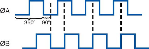
This and the lack of 90 degree phase shift will make quadrature operation
especially at higher speeds where the symmetry is worse, difficult.
You might adjust the opto sensor thresholds for closer to 50% duty cycle
as this would likely improve the maximum RPM
at over 100 RPM or so due to the low sample frequency (952 hz)
So if you want to adjust the phase angle or symmetry with halscope
you should do it at a very low speed. A real oscilloscope would allow
you to check these at high speeds.
My guess is that the pulses start to disappear at 2200 RPM or so
You can see that they are unsymmetrical.(unequal high and low state times)
This and the lack of 90 degree phase shift will make quadrature operation
especially at higher speeds where the symmetry is worse, difficult.
You might adjust the opto sensor thresholds for closer to 50% duty cycle
as this would likely improve the maximum RPM
Last edit: 28 Sep 2020 23:23 by PCW.
Please Log in or Create an account to join the conversation.
- fenolski
- Offline
- New Member
-
Less
More
- Posts: 12
- Thank you received: 0
29 Sep 2020 07:06 #184245
by fenolski
Replied by fenolski on topic 7i76E spindle encoder - strange readouts
@OT-CNC Yes, Linux counts rotations upwards and downwards.
@PWC. Could you please tell me what you mean "adjust opto sensor treshold"
I did "90deg optimalisation" during a gluing the sensors. I rotated them smoothly till I got proper readouts in LinuxCNC. Up to 2.2k rpm the readouts are perfect. After lowpass filtration, compared to handheld RPM meter the difference is about 1%. Isn't also strange that in "counter mode", where LCNC takes only A signal into consideration, readouts behave in the same manner?
Please Log in or Create an account to join the conversation.
- PCW
-
- Offline
- Moderator
-
Less
More
- Posts: 17996
- Thank you received: 5283
29 Sep 2020 13:47 #184291
by PCW
Replied by PCW on topic 7i76E spindle encoder - strange readouts
The threshold is when the output switches relative to the amount of light
You can also adjust this with the LED intensity. In any case, this should be
adjusted for 50% duty cycle. The dropout over 2000 RPM or so is
possibly because the pulse width become so narrow it disappears
Another possibility is that you did not disconnect the "B" input when using
counter mode so faulty quadrature would cause count aberrations.
Please Log in or Create an account to join the conversation.
- fenolski
- Offline
- New Member
-
Less
More
- Posts: 12
- Thank you received: 0
29 Sep 2020 23:52 #184337
by fenolski
Replied by fenolski on topic 7i76E spindle encoder - strange readouts
To change the threshold I need to modify electronic circuits eg. change resistors or there is a different way? I there any example how to build a proper optosensor? Maybe these I bought are too slow.
I checked the spindle-vel-fb-rps readouts when the spindle was stopped. Halmeter was showing fluctuating non zero values. What could be a reason?
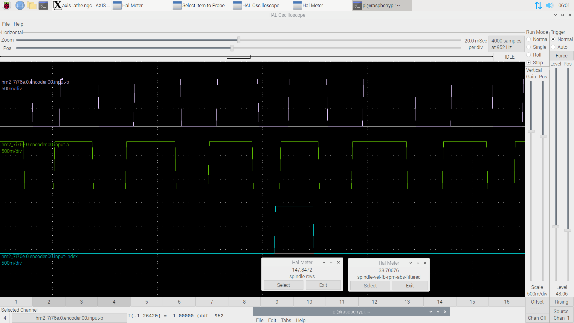
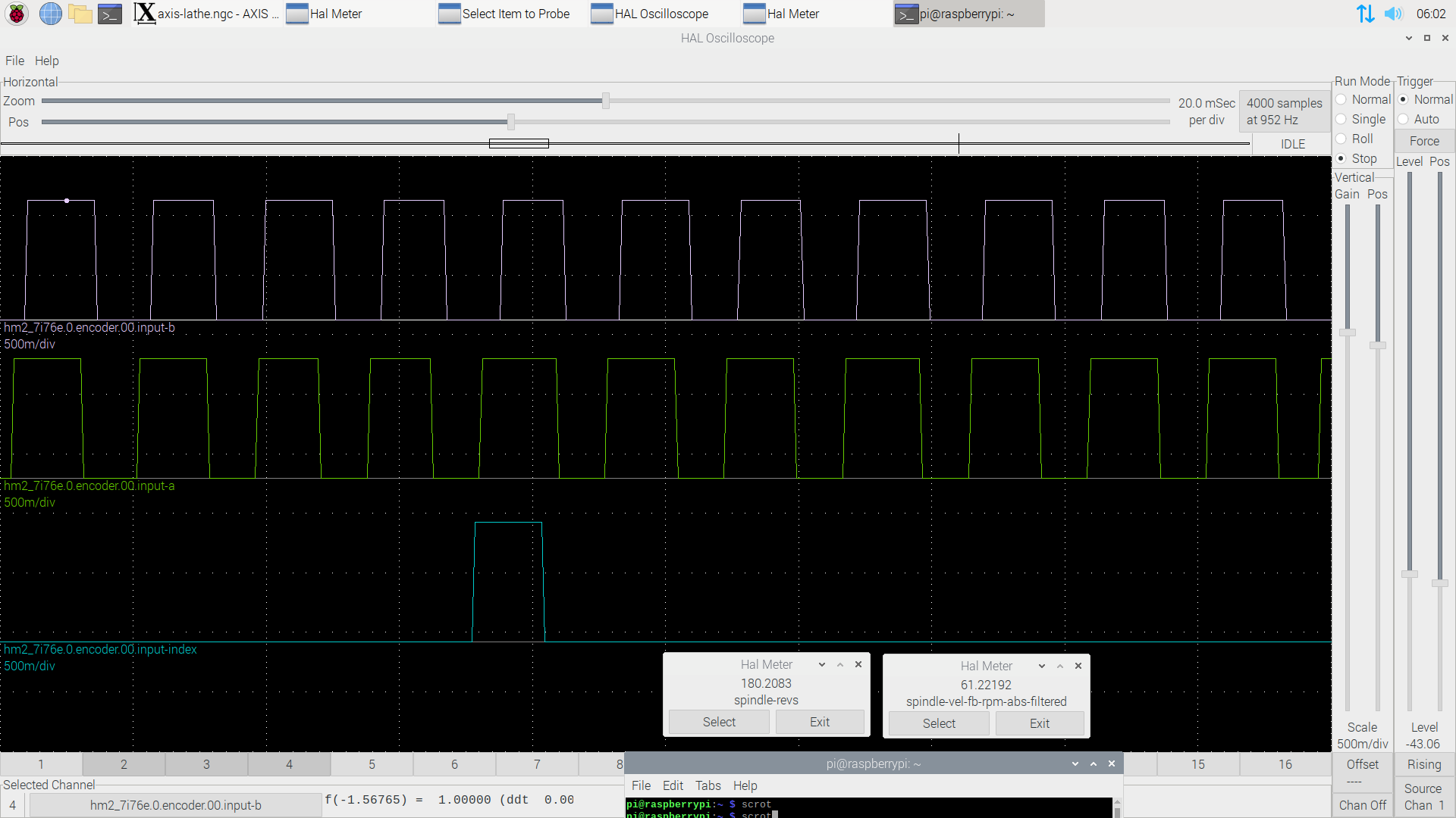
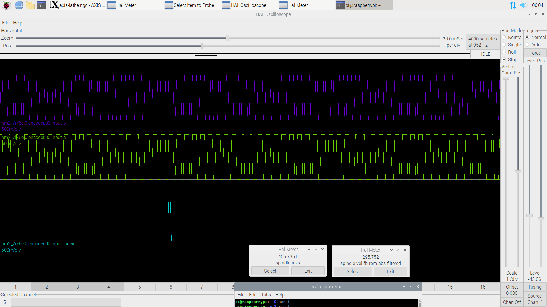
Regarding A/B alignment. Below you can find Halscope readouts at slower speeds. There is a phase shift between A and B.
I checked the spindle-vel-fb-rps readouts when the spindle was stopped. Halmeter was showing fluctuating non zero values. What could be a reason?
Regarding A/B alignment. Below you can find Halscope readouts at slower speeds. There is a phase shift between A and B.
Attachments:
Please Log in or Create an account to join the conversation.
Time to create page: 0.495 seconds