Lathe Bed Wear Compensation
- fjcarroll
- Offline
- New Member
-

Less
More
- Posts: 3
- Thank you received: 0
21 Mar 2021 20:06 #203150
by fjcarroll
Lathe Bed Wear Compensation was created by fjcarroll
Hello!
I've just bought a nice Profitmaster 15x40 inch lathe that I intend to convert to CNC. This will be my second experience retrofitting/converting a machine using LinuxCNC so I'm fairly familiar with HAL setup, servo/drive selection etc.
The saddle ways some amount of wear, but not a huge amount (no wear ridges etc) while the tailstock ways appear to be unworn except at the very extreme end of the Z travel.
It's fairly easy to get a good indication of the saddle way wear purely in the Y axis at various points along the Z axis using a test bar and indicator on the top surface (pitch error), and the differential wear (roll error) in the saddle bed using two indicators mounted to the saddle at a fixed distance that indicate on the (relatively) unworn tailstock ways. From there, using some trig it's trivial to calculate the necessary X offset needed to turn a "true" cylinder of any size at any point along Z that you've recorded data for. I can also indicate the side of the test bar to further compensate if there is a spindle to carriage way parallelism error that varies along Z (yaw error, if the error is constant it would likely be a spindle alignment issue while a variable error would be wear.)
My question is, how would I implement these compensations? I have used millkins to compensate for perpendicularity errors before, but not parallelism, and the only thread I've seen for lathe bed wear compensation has been inactive for nearly two years with only small snippets of code posted. Unfortunately I have not written a HAL component before and I'm fairly lost as to where I should start. I would appreciate any help greatly. In the mean time I will be looking at the millkins code to get some idea of how this could work.
Thank you,
-Forrest Carroll
Please Log in or Create an account to join the conversation.
- andypugh
-

- Offline
- Moderator
-

Less
More
- Posts: 19875
- Thank you received: 4642
21 Mar 2021 20:49 #203155
by andypugh
Replied by andypugh on topic Lathe Bed Wear Compensation
I would use a combination of "lincurve" and "external offsets"
linuxcnc.org/docs/2.8/html/man/man9/lincurve.9.html
linuxcnc.org/docs/2.8/html/motion/external-offsets.html
The only wrinkle is that lincurve outputs float and EO expects s32 counts, so there needs to be a scaling-up then a scaling-down again. And a type conversion: linuxcnc.org/docs/2.8/html/man/man9/conv_float_s32.9.html
Please Log in or Create an account to join the conversation.
- fjcarroll
- Offline
- New Member
-
Less
More
- Posts: 3
- Thank you received: 0
23 Mar 2021 15:09 - 23 Mar 2021 16:01 #203398
by fjcarroll
Replied by fjcarroll on topic Lathe Bed Wear Compensation
I wanted to make sure I have the math correct before implementing it further.
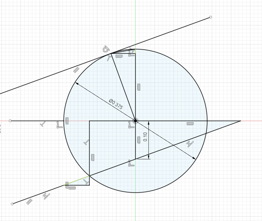
With the measured centerline height offset (b, generally a negative value) and measured bed slope (m, unitless as in/in) the equation for the line the tool will draw as it moves along the axis is y=mx + b, this will give you the height offset from origin at any point along the travel of the carriage. The equation for a circle is x^2 + y^2=r^2, r here being the radius of the work we intend to cut. Substituting mx+b for y in this equation and doing some algebra you can arrive at x=(-mb + sqrt(r^2 + m^2r^2 - b^2))/(m^2 + 1) and x=-((mb + sqrt(r^2 + m^2r^2 - b^2))/(m^2+1) for the general intercepts of the line and the circle. We can ignore the negative value as in the normal case we will be working only in positive x values. With this info we can calculate r-x as the difference between the radius of the work we intend to cut and the radius we need to cut, or the distance between where the tool is and where the tool should be. Note here that the x value is along the ideal axis and not along the axis that the carriage is moving along. To get the value along the x axis we calculate (correction value) = x/cos(arctan(m)). arctan(m) converts the slope into degrees to work with cosine. This value would be subtracted from joints[0] (x) as it is the distance we need to move in the _negative_ direction to meet the circle.
Note that we also need to correct measured centerline height offsets via another method, when sweeping across the top of a test bar with a lathe that has differential wear, the high reading will be at the tangency point between the line the indicator travels and the test bar and NOT the point where the ideal Y axis intersects the top of the test bar. Since we know the slope the line is moving along and the diameter of the test bar, this correction is trivial to calculate. r*sin(arctan(m)) = opp, opp*tan((arctan(m)/2)) = hcorr
The other misalignments that can occur: z axis to work skew, x axis to z skew. X axis to z skew is easy to implement, it is simply multiplying x by the unitless skew error (in/in) between x and z. Work to z skew would be more complex and requires both x and z to be compensated. The z compensation would be a scaling of zactual=z/cos(arctan(zskew)) and the x compensation would be z*zskew=xzcomp. Work to z axis misalignment is _likely_ to fail, and I may not implement it. Getting the headstock and tailstock aligned with the ways is critical, and if the error is in the wrong direction you would end up making bad parts even with compensation.
Onto some programming questions.
Is it acceptable to use fopen in a component? I would like to load the measured data from a file containing an array of floats represented as strings, then strtof these into an array. Doing this is easy enough but I don't know that it's an acceptable method.
I am also not sure after that is done just how to pass the correction off to external offsets. By scaling up and scaling down I assume you mean multiplying the correction by 1000.0f, dividing by 1000.0f (as I saw in the other lathe bed wear compensation post) which should also cast the float to an integer that can be passed off to eo, correct?
Unfortunately I'm not much of a programmer, I'm sure I will have questions and (bad) code that needs looked over as I progress with this.
EDIT:
This compensation fails when the line no longer intercepts the intended circle to be cut or becomes tangent to the circle to be cut. This can be checked using the determinant described here mathworld.wolfram.com/Circle-LineIntersection.html, and if the line no longer intercepts the intended circle the compensation will not be performed and the x value requested will simply be passed through (in the case you are facing or cutting off a part and pass through the center to ensure it is cleaned up.)
EDIT 2:
You should also record the distance needed to move x to hit the tangent high point, this will be a direct offset subtracted to x in the case the bed slope is causing the x to move away from the work in the "true" x axis (ie, the bed pivot is not directly below the work centerline.) Am I correct in thinking this?
Attachments:
Last edit: 23 Mar 2021 16:01 by fjcarroll.
Please Log in or Create an account to join the conversation.
- andypugh
-
- Offline
- Moderator
-
Less
More
- Posts: 19875
- Thank you received: 4642
23 Mar 2021 22:31 #203450
by andypugh
Replied by andypugh on topic Lathe Bed Wear Compensation
Your mathematical approach will tend to fail if the tool is not exactly on the centreline. And it seems likely that the variation in tool height setting might well swamp height changes due to bed wear.
I suspect that the practical solution is the experimental one, measure a test bar using an indicator in the toolpost.
RTAI realtime components are kernel modules and have no access to the filesystem.
This limitation might be relaxed with preempt-rt and usepace, I haven't checked.
What I would suggest is using Python code to load a lincurve and set up its coefficients from a file.
(Actually, if you are coding then I would suggest modifying lincurve to output s32 counts directly, for consumption by the external offsets)
lincurve is here: github.com/LinuxCNC/linuxcnc/blob/master...onents/lincurve.comp
It would be easy to increase the maximum number of points, and you can change the output pin to "signed" and change line 61 to something like
This doc explains the .comp file format:
linuxcnc.org/docs/2.8/html/hal/comp.html
I suspect that the practical solution is the experimental one, measure a test bar using an indicator in the toolpost.
RTAI realtime components are kernel modules and have no access to the filesystem.
This limitation might be relaxed with preempt-rt and usepace, I haven't checked.
What I would suggest is using Python code to load a lincurve and set up its coefficients from a file.
(Actually, if you are coding then I would suggest modifying lincurve to output s32 counts directly, for consumption by the external offsets)
lincurve is here: github.com/LinuxCNC/linuxcnc/blob/master...onents/lincurve.comp
It would be easy to increase the maximum number of points, and you can change the output pin to "signed" and change line 61 to something like
out_ = 100000 * y_val(i) + f * (y_val(i+1) - y_val(i));This doc explains the .comp file format:
linuxcnc.org/docs/2.8/html/hal/comp.html
Please Log in or Create an account to join the conversation.
- matasbuk
- Offline
- Junior Member
-

Less
More
- Posts: 34
- Thank you received: 3
22 Feb 2026 17:37 #343315
by matasbuk
Replied by matasbuk on topic Lathe Bed Wear Compensation
Hi,
did you manage to get the compensation working? I also have a bed wear problem on my lathe and wondering if there are any software solutions?
did you manage to get the compensation working? I also have a bed wear problem on my lathe and wondering if there are any software solutions?
Please Log in or Create an account to join the conversation.
- arijitdutta
- Offline
- Junior Member
-
Less
More
- Posts: 29
- Thank you received: 3
28 Feb 2026 09:11 #343643
by arijitdutta
Replied by arijitdutta on topic Lathe Bed Wear Compensation
Got something done regarding the compensation with my own approach. How bad is the wear and are you getting any tapers?
Please Log in or Create an account to join the conversation.
- matasbuk
- Offline
- Junior Member
-
Less
More
- Posts: 34
- Thank you received: 3
03 Mar 2026 20:51 #343815
by matasbuk
Replied by matasbuk on topic Lathe Bed Wear Compensation
Its about 0.17mm along the whole Z axis. Mostly near the chuck as always. Could you perhaps share a bit of what you had done? Attaching the picture of my bed wear.
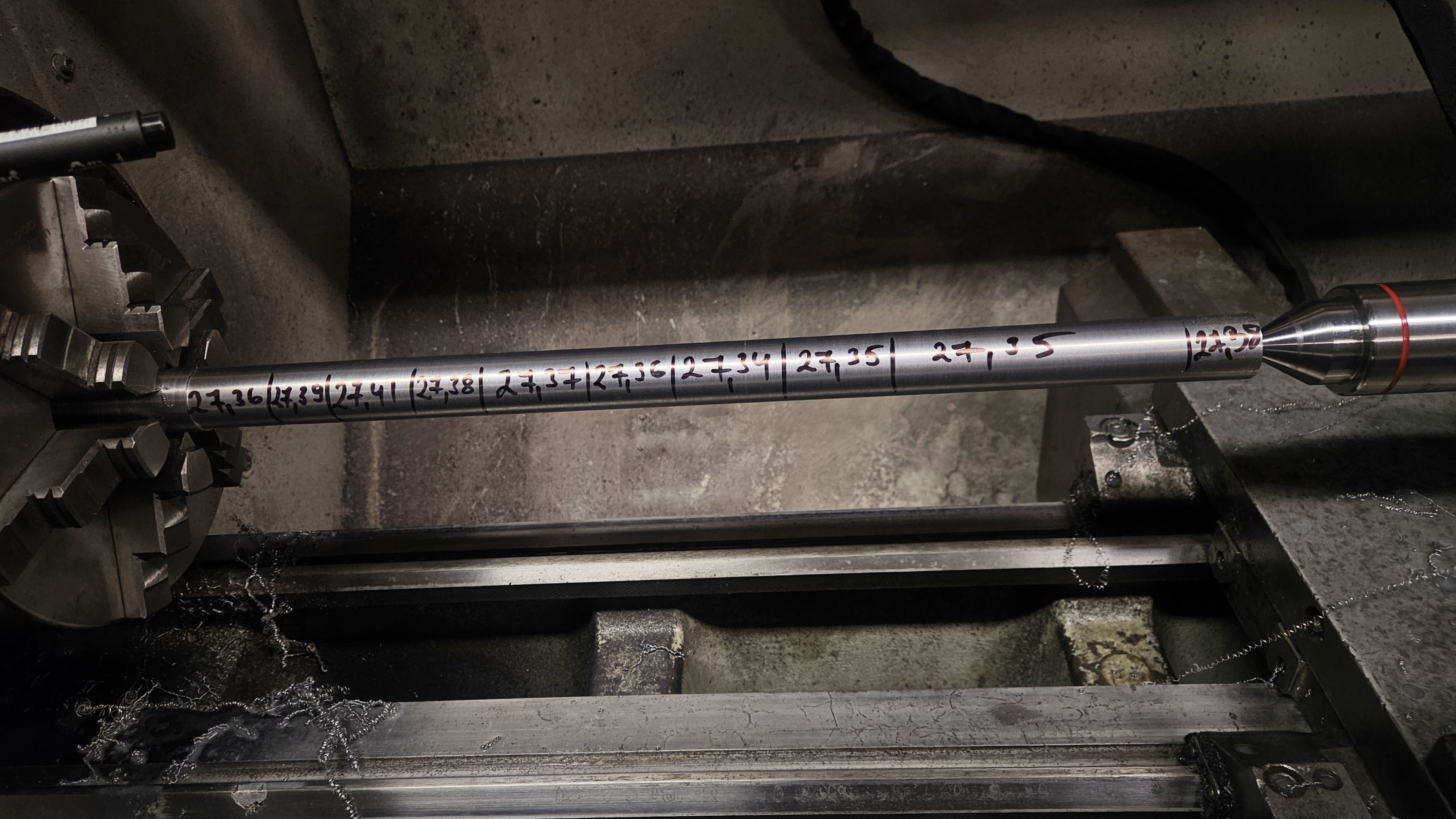
Attachments:
Please Log in or Create an account to join the conversation.
- arijitdutta
- Offline
- Junior Member
-
Less
More
- Posts: 29
- Thank you received: 3
04 Mar 2026 05:40 #343825
by arijitdutta
Replied by arijitdutta on topic Lathe Bed Wear Compensation
thats pretty negligible to what i have. mine is far far worse. will share as soon as i get to my shop.
Please Log in or Create an account to join the conversation.
- andypugh
-
- Offline
- Moderator
-
Less
More
- Posts: 19875
- Thank you received: 4642
05 Mar 2026 17:06 #343902
by andypugh
Replied by andypugh on topic Lathe Bed Wear Compensation
The compensation needs to allow for tilt of the saddle as it moves along the bed. There is typically more wear on the front way than the rear, and this is (I believe) what causes the machined diameter to vary.
You could measure a parallel test bar with a dial indicator at various points along the bed, and use the "lincurve" component to calculate the required offset (and then add that on between motor-pos-cmd and and the input to the PID)
You could measure a parallel test bar with a dial indicator at various points along the bed, and use the "lincurve" component to calculate the required offset (and then add that on between motor-pos-cmd and and the input to the PID)
Please Log in or Create an account to join the conversation.
Time to create page: 0.413 seconds