Hi Guys,
It's been a long time since the last update. At least 5 versions of linuxcnc

I have done some interesting modifications to the machine.
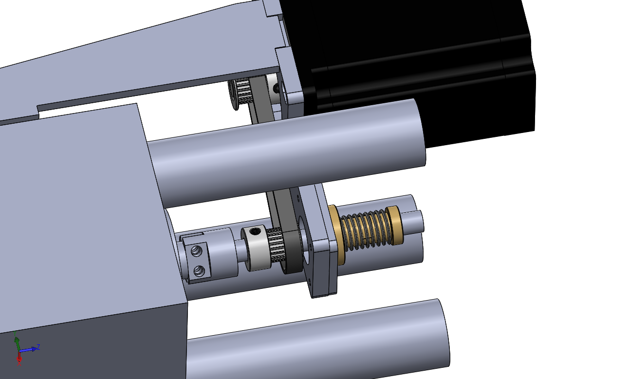
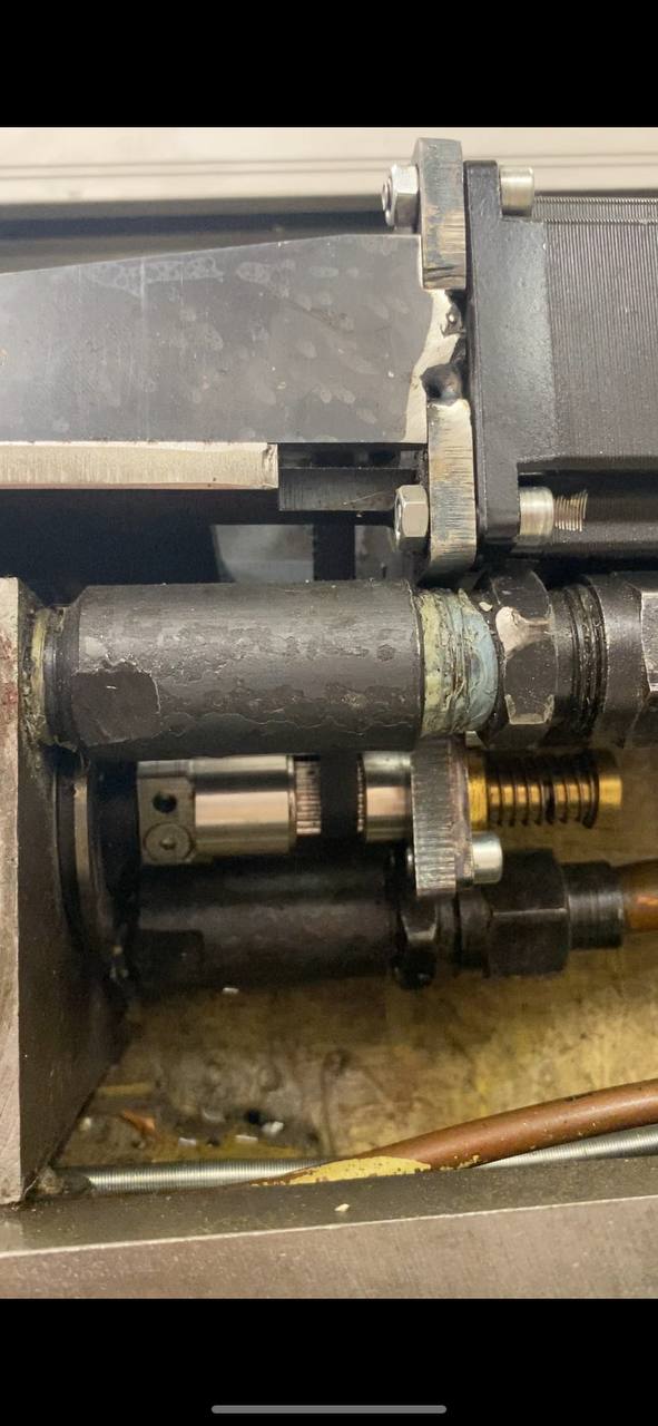
I have attached the valve shaft to a lead screw with backlash compensated nut.
Later, I am going to replace that with the Ball Screw.
Then, the valve is moved via a timing belt connected to the stepper motor.
With a 2mm screw pitch It is possible to locate valve shaft with decent acuracy.
Please see the attached picture.
For the past couple of weeks, I've been trying to tune the PID for that setup. But it is hard.
It oscillates a lot, or it is not compensating the steady state error.
I would love to hear your advice on a couple of points:
1) What is the typical following error for an axis with a linear scale of 0.001mm resolution(1 micron)? In steady state it is able to position the axis within +-0.005 accuracy. Do you think it is possible to get more from that scale resolution?
During acceleration and deceleration, an error jumps up to 0.1mm at 1500mm/min speed. What is a typical result for well well-tuned PID loop?
2) Do you think I should set up a two-stage PID control loop? One stage is to control the position of the valve shaft based on the velocity feedback from the scale. And that another loop to control the position and give a commanded velocity as an output?
Thank you!
PS. I do have some videos that I can share in case you are interested.