linear scale and AC servo set up - sanity check
- andypugh
-

- Offline
- Moderator
-

Less
More
- Posts: 19876
- Thank you received: 4642
15 Oct 2022 14:55 #254174
by andypugh
Replied by andypugh on topic linear scale and AC servo set up - sanity check
That looks basically OK.
(I assume that you have not homed? I think that there may be problems to fix with homing)
If you open a couple of halmeters on pid.x-external.command and pid.x-external.feedback and then add a tiny amount of I gain, does the feedback tend towards the command, or away?
You can do this from the tuning GUI or command line, I prefer to open a hal prompt where I can manipulate the hal pins directly with tab-completion.
for example.
In the data you show there is about .25 mm (inch?) difference between commanded and the scale feedback. Does that sound likely?
(I assume that you have not homed? I think that there may be problems to fix with homing)
If you open a couple of halmeters on pid.x-external.command and pid.x-external.feedback and then add a tiny amount of I gain, does the feedback tend towards the command, or away?
You can do this from the tuning GUI or command line, I prefer to open a hal prompt where I can manipulate the hal pins directly with tab-completion.
halcmd -kf
loadusr halmeter pin pid.x_external.command
loadusr halmeter pin pid.x_external.feedback
setp pid.x_external.Igain 0.0001In the data you show there is about .25 mm (inch?) difference between commanded and the scale feedback. Does that sound likely?
The following user(s) said Thank You: chienMouille
Please Log in or Create an account to join the conversation.
- chienMouille
- Offline
- Senior Member
-

Less
More
- Posts: 73
- Thank you received: 3
16 Oct 2022 10:15 #254211
by chienMouille
Replied by chienMouille on topic linear scale and AC servo set up - sanity check
Ok, I did this test. I was about to write something else because I was basically misinterpreting the data. Essentially when I add substantial I(ext) gain, the motor does move to compensate the backlash. If i increase it all the way to 150, it even does this rather fast. (at 0.5 it just shoots the 0.75mm and then moves very slowly towards the commanded position and reaches the 0.25 gap in a couple of minutes, which I intially interpreted as running away).
However, at 150 the axis does rattle a lot in longer moves. Like it's way too stiff. Which is very similar to the results I was getting with the single loop feedback: either too slow to compensate either too stiff. The main difference I would say is that in the current setup it doesn't tend to overshoot (it does at 150 but by 5um).
Yes, the trapezoidal screw backlash is about 0.25mm (metric machine).
Please Log in or Create an account to join the conversation.
- andypugh
-
- Offline
- Moderator
-
Less
More
- Posts: 19876
- Thank you received: 4642
16 Oct 2022 18:24 #254249
by andypugh
Replied by andypugh on topic linear scale and AC servo set up - sanity check
Sorry, I meant to reply much earlier.
You might be able to manage a higher I gain if you limit the max-error.
Look at pid.x_external.maxerror and pid.x_external.maxerrorI
The value is the distance in mm at which you want the max correction output. So possibly something like 0.05mm.
You can also try adding a bit of Pgain, that should speed things up a bit.
Please Log in or Create an account to join the conversation.
- chienMouille
- Offline
- Senior Member
-
Less
More
- Posts: 73
- Thank you received: 3
17 Oct 2022 09:18 #254317
by chienMouille
Replied by chienMouille on topic linear scale and AC servo set up - sanity check
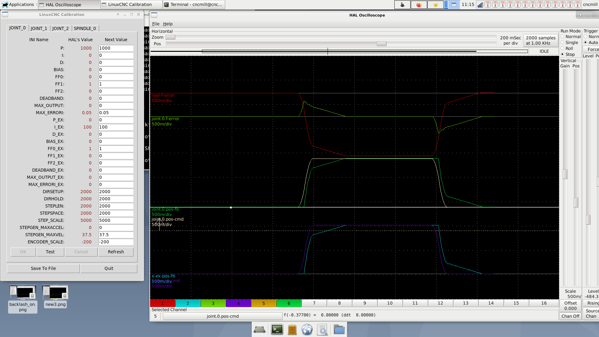
it still rattles quite a bit.
changing the max_errorI(ext) was canceling the backlash comp of the second loop, changing the max_errorI(int) seemed to calm slightly the rattling.
here are values and a scope:
changing the max_errorI(ext) was canceling the backlash comp of the second loop, changing the max_errorI(int) seemed to calm slightly the rattling.
here are values and a scope:
Attachments:
Please Log in or Create an account to join the conversation.
- andypugh
-
- Offline
- Moderator
-
Less
More
- Posts: 19876
- Thank you received: 4642
17 Oct 2022 09:31 #254318
by andypugh
Replied by andypugh on topic linear scale and AC servo set up - sanity check
I don't know what your "real-ferror" calculation is, but your steady-state f-error.0 (difference between linear scale and commanded) is actually very good for a machine with sloppy leadscrews.
I would not expect maxerrorI on the int pid to have any effect, as there is no I gain, so hence no I-term to limit.
The next stage is a lot more tuning, perhaps adding some P gain to the ext, a bit of FF1 etc, while looking at the traces to see what the effect is.
It's an art, not a science at this point. Well. maybe a scientific art")
I would not expect maxerrorI on the int pid to have any effect, as there is no I gain, so hence no I-term to limit.
The next stage is a lot more tuning, perhaps adding some P gain to the ext, a bit of FF1 etc, while looking at the traces to see what the effect is.
It's an art, not a science at this point. Well. maybe a scientific art
Please Log in or Create an account to join the conversation.
- chienMouille
- Offline
- Senior Member
-
Less
More
- Posts: 73
- Thank you received: 3
18 Oct 2022 10:49 #254388
by chienMouille
Replied by chienMouille on topic linear scale and AC servo set up - sanity check
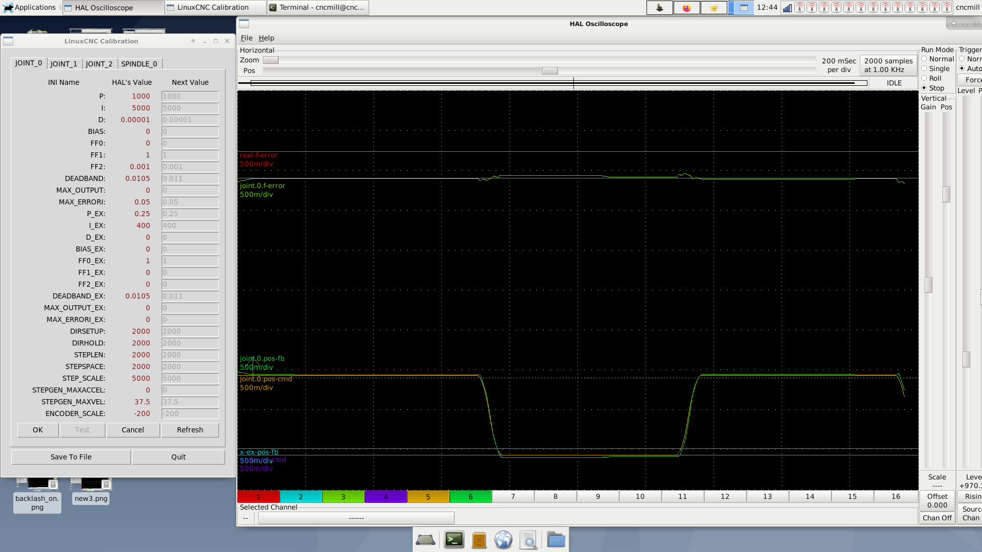
I got here, with much less rattling (though still a bit at some points on long rapid moves).
And a bit of overshoot on moves with no direction change.
I dont understand what the vertical divisions of the scopes actually show. It's kinda dump question, but thus I don't get what the error scale actually is in the real world. Would you enlighten me?
(also I tried to activate software backlash comp, thinking that it could maybe operate only on the interior loop, and thus give a result close to idea in my earlier drawing, but it doesn't seem to actually have any effect)
Attachments:
Please Log in or Create an account to join the conversation.
- andypugh
-
- Offline
- Moderator
-
Less
More
- Posts: 19876
- Thank you received: 4642
18 Oct 2022 11:14 #254391
by andypugh
Replied by andypugh on topic linear scale and AC servo set up - sanity check
The f-error scale is 500m/div, which is 0.5 units per division.
You can change this for each channel with the gain slider on the right.
It looks to me like your f-error is around 1/10 of a division now, so about 50 microns / 2 thousandths of an inch.
But this looks like a step-change? It might be instructive to halscope some actual G-code at cutting speed, it will probably look a bit better.
Please Log in or Create an account to join the conversation.
- andypugh
-
- Offline
- Moderator
-
Less
More
- Posts: 19876
- Thank you received: 4642
18 Oct 2022 11:16 #254392
by andypugh
Replied by andypugh on topic linear scale and AC servo set up - sanity check
Also, bear in mind that this error is along the line of cut, so only sometimes does it translate to a part geometry error of the same magnitude.
Please Log in or Create an account to join the conversation.
- chienMouille
- Offline
- Senior Member
-
Less
More
- Posts: 73
- Thank you received: 3
18 Oct 2022 12:07 - 18 Oct 2022 12:13 #254395
by chienMouille
Replied by chienMouille on topic linear scale and AC servo set up - sanity check
alright, yes, I wasn't getting what unit. so millimeters yes?
yes for now i'm just jogging back and forth 1mm.
and doing some long rapid moves every now and then to check the stiffness (rattling).
all this at 1800mm/m
yes for now i'm just jogging back and forth 1mm.
and doing some long rapid moves every now and then to check the stiffness (rattling).
all this at 1800mm/m
Last edit: 18 Oct 2022 12:13 by chienMouille.
Please Log in or Create an account to join the conversation.
- chienMouille
- Offline
- Senior Member
-
Less
More
- Posts: 73
- Thank you received: 3
18 Oct 2022 12:08 #254396
by chienMouille
Replied by chienMouille on topic linear scale and AC servo set up - sanity check
i'll check with some actual cuts soon, thanks! still making a bracket for the Y servo, so not totally operational for cutting
Please Log in or Create an account to join the conversation.
Time to create page: 0.204 seconds