Orientation spindle for toolchange - gearbox
- greg23_78
- Offline
- Premium Member
-

Less
More
- Posts: 142
- Thank you received: 7
30 Nov 2023 21:12 #286906
by greg23_78
Orientation spindle for toolchange - gearbox was created by greg23_78
Hi,
I'm trying to implement a spindle orientation in my configuration to end up with a tool change.
I don't know where to start.
Config :
2 speeds - 1:1 and 1:2 ratio
Ac servo spindle (with encoder)
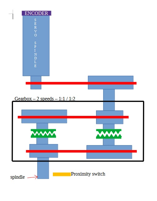
1) Can I use the orient component (A and B on the encoder and index on the sensor) with a gearbox?
2) if I use a system where M19 is requested, turning the spindle gently (low frequency + speed ratio 1:2) and stopping when the sensor is active, will my system be accurate enough? (it's a big machine so the max rpm spindle is 1500rpm)
like this
I'm trying to implement a spindle orientation in my configuration to end up with a tool change.
I don't know where to start.
Config :
2 speeds - 1:1 and 1:2 ratio
Ac servo spindle (with encoder)
1) Can I use the orient component (A and B on the encoder and index on the sensor) with a gearbox?
2) if I use a system where M19 is requested, turning the spindle gently (low frequency + speed ratio 1:2) and stopping when the sensor is active, will my system be accurate enough? (it's a big machine so the max rpm spindle is 1500rpm)
like this
O100 IF [#5000 EQ 0]
    M2 S100
    G4 P2
    #5000 = 10
O100 ENDIIF
Attachments:
Please Log in or Create an account to join the conversation.
- andypugh
-

- Offline
- Moderator
-

Less
More
- Posts: 19886
- Thank you received: 4645
09 Dec 2023 10:53 #287635
by andypugh
Replied by andypugh on topic Orientation spindle for toolchange - gearbox
Is this a home-built machine, or a conversion of a commercial machine?
If it is the latter, then presumably the design is capable of working.
One way to align accurately might be to attempt to align to zero encoder-counts with a PID, after setting the encoder-index flag.
Initially the spindle will be many turns away from zero, so will spin fairly fast. On the first pass past the prox the encoder counts will zero, and the PID output will reduce the speed, and should finally settle to fairly exactly where the prox triggered.
This assumes that the spindle turns predominantly in one direction, so that the pid causes the spindle to approach the prox in the opposite direction, otherwise there is a chance of a prox-width error.
Please Log in or Create an account to join the conversation.
- andypugh
-
- Offline
- Moderator
-
Less
More
- Posts: 19886
- Thank you received: 4645
09 Dec 2023 10:54 - 09 Dec 2023 10:55 #287636
by andypugh
Replied by andypugh on topic Orientation spindle for toolchange - gearbox
Forgot to say, you should use the prox sensor output as the encoder Z channel. Not the index on the encoder itself.
And you should limit the PID maxoutput to a sensible speed, too.
And you should limit the PID maxoutput to a sensible speed, too.
Last edit: 09 Dec 2023 10:55 by andypugh.
Please Log in or Create an account to join the conversation.
Time to create page: 0.100 seconds