PID tuning step & dir servos?
- spumco
- Offline
- Platinum Member
-

Less
More
- Posts: 2126
- Thank you received: 882
03 Dec 2023 04:17 #287065
by spumco
PID tuning step & dir servos? was created by spumco
Could use some guidance from the community. First time using linear scale feedback and tuning LCNC's PID.
Manually adjusting and watching halscope here's where I am:
P=125
I=200
D=0.3
FF0=0
FF1=1
FF2=0.006
FF3=0
deadband=0.0005 to stop a little dither
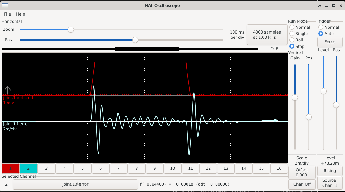
Attached is a 1" move at 200ipm.
What is the "f(-0.18200) = -0.00001 (ddt 0.00000)" value in halscope? When I hover over the trace, the maximum value of the largest peak is 0.00628.
Does that mean 0.00628" of error at that point?
Am I on the right track?
Any suggestions on tightening up the f-error?
- 1kw S&D servos
- drives set/tuned internally to be as stiff as possible without noise/vibration
- 1um glass scales
- scale FB sent to PID FB (loop is closed)
- Lathe Z-axis
- ~75lbs of mass
- 5mm ballscrews
- MAX_ACCEL = 400 in INI and for stepgen
Manually adjusting and watching halscope here's where I am:
P=125
I=200
D=0.3
FF0=0
FF1=1
FF2=0.006
FF3=0
deadband=0.0005 to stop a little dither
Attached is a 1" move at 200ipm.
What is the "f(-0.18200) = -0.00001 (ddt 0.00000)" value in halscope? When I hover over the trace, the maximum value of the largest peak is 0.00628.
Does that mean 0.00628" of error at that point?
Am I on the right track?
Any suggestions on tightening up the f-error?
Attachments:
Please Log in or Create an account to join the conversation.
- tommylight
-

- Away
- Moderator
-

Less
More
- Posts: 21767
- Thank you received: 7440
03 Dec 2023 12:07 #287087
by tommylight
Replied by tommylight on topic PID tuning step & dir servos?
Just to be on the safe side, is all set and working properly without feedback to LinuxCNC?
I seems way to high, start from 0, same for D and FF2
FF1 will most probably not be 1, except if you have the output scaling done based on max velocity of servos/motors.
Use a wee bit of FF2 only if you still have spikes at start/end of move after testing the above.
I seems way to high, start from 0, same for D and FF2
FF1 will most probably not be 1, except if you have the output scaling done based on max velocity of servos/motors.
Use a wee bit of FF2 only if you still have spikes at start/end of move after testing the above.
Please Log in or Create an account to join the conversation.
- spumco
- Offline
- Platinum Member
-
Less
More
- Posts: 2126
- Thank you received: 882
03 Dec 2023 15:02 #287101
by spumco
Replied by spumco on topic PID tuning step & dir servos?
@Tommy,
- Yes, it's working reasonably well open loop.
- For I, the auto-tune came up with a silly 3000.0 or so. I dialed it way back, and also found a comment from PCW regarding a similar S&D configuration:
Also I would not expect the I terms to do
much of anything if less than 1000 or so- FF1 - Steps/inch is 50810, and INPUT_SCALE = 25398, so I'm guessing I need to drop it from 1.0 to 0.5 to start?
- FF2 and FF3 both seem to help with the initial spikes, but I'll work on the above first.
The following user(s) said Thank You: tommylight
Please Log in or Create an account to join the conversation.
- spumco
- Offline
- Platinum Member
-
Less
More
- Posts: 2126
- Thank you received: 882
04 Dec 2023 21:48 - 04 Dec 2023 21:54 #287219
by spumco
Replied by spumco on topic PID tuning step & dir servos?
Best I can do so far at F50 (ipm). X-axis is a bit better.
Is the "0.00299" in halscope (the start peak) 0.0029 inches? Or some other value?
Also wondering if the wobble during steady state is the internal drive tuning and there's nothing I can do about that in LCNC.
I and D didn't seem to make anything better. Tried really low number up to I >4000.
Any sugestions?
EDIT- added X-scope for comparison
Last edit: 04 Dec 2023 21:54 by spumco. Reason: Added X
Please Log in or Create an account to join the conversation.
- PCW
-

- Away
- Moderator
-
Less
More
- Posts: 17997
- Thank you received: 5284
04 Dec 2023 22:18 - 04 Dec 2023 22:19 #287223
by PCW
Replied by PCW on topic PID tuning step & dir servos?
I suspect error spike is because of the delay from command to motion
in the drives. Unless that is something you can improve in the drive tuning,
the only other options I can think of are:
1. Reduce the acceleration. I would expect the peak error to be roughly
proportional to acceleration.
2. Use open loop (and assume the drive delays are the same
for both axis)
3. Encourage the people working on a jerk limited TP
Last edit: 04 Dec 2023 22:19 by PCW.
The following user(s) said Thank You: rodw, spumco
Please Log in or Create an account to join the conversation.
- spumco
- Offline
- Platinum Member
-
Less
More
- Posts: 2126
- Thank you received: 882
05 Dec 2023 01:17 #287231
by spumco
I did notice improvement when I cut down the accel. But I'm greedy and want a fast machine.
I've got garbage ballscrews, and no hope of hitting decent tolerance without the scales.
I'm running out of 'thumbs-up' in the couple of jerkTP threads.

I'll fiddle with the drive internal settings, thanks.
Replied by spumco on topic PID tuning step & dir servos?
1. Reduce the acceleration. I would expect the peak error to be roughly
proportional to acceleration.2. Use open loop (and assume the drive delays are the same
for both axis)3. Encourage the people working on a jerk limited TP
I'll fiddle with the drive internal settings, thanks.
The following user(s) said Thank You: tommylight, rodw
Please Log in or Create an account to join the conversation.
- tommylight
-
- Away
- Moderator
-
Less
More
- Posts: 21767
- Thank you received: 7440
05 Dec 2023 01:27 #287233
by tommylight
Replied by tommylight on topic PID tuning step & dir servos?
Are the ball screws that bad to cause all the wavy feedback between spikes?
If not, fix that first, then chase spikes. Feedback should track pretty flat during motion at constant speed.
If not, fix that first, then chase spikes. Feedback should track pretty flat during motion at constant speed.
Please Log in or Create an account to join the conversation.
- spumco
- Offline
- Platinum Member
-
Less
More
- Posts: 2126
- Thank you received: 882
05 Dec 2023 03:38 #287237
by spumco
No Tommy, they're not that bad. I was exaggerating - they're remarkably good for Amazon. About +/-5um along 300mm according to the encoders.
I think the waves are from the drive; it's got a 'real-time' auto tuning feature I left enabled.
After taking PCW's advice and fidding with the drive's settings I knocked the f-error in half for both axes. They sound nice, no dithering, pretty stiff.
I'll wait to get tools installed and take some cuts before circling back to see if it needs improvement.
Replied by spumco on topic PID tuning step & dir servos?
Are the ball screws that bad to cause all the wavy feedback between spikes?
If not, fix that first, then chase spikes. Feedback should track pretty flat during motion at constant speed.
No Tommy, they're not that bad. I was exaggerating - they're remarkably good for Amazon. About +/-5um along 300mm according to the encoders.
I think the waves are from the drive; it's got a 'real-time' auto tuning feature I left enabled.
After taking PCW's advice and fidding with the drive's settings I knocked the f-error in half for both axes. They sound nice, no dithering, pretty stiff.
I'll wait to get tools installed and take some cuts before circling back to see if it needs improvement.
The following user(s) said Thank You: tommylight
Please Log in or Create an account to join the conversation.
Time to create page: 0.609 seconds