P1 expansion port
- Bl484
- Offline
- Junior Member
-

Less
More
- Posts: 21
- Thank you received: 0
05 Dec 2023 02:08 - 05 Dec 2023 02:12 #287234
by Bl484
P1 expansion port was created by Bl484
Hi,
I am curious to determine if it is possible to use the P1 expansion port pins as an output for the step-generated signal through a specific command in my Hal file. I attempted this by using the following command.
setp hm2_7i96s.0.gpio.041.is_output true
net stp_X hm2_7i96s.0.gpio.017.in hm2_7i96s.0.gpio.041.out
setp hm2_7i96s.0.gpio.042.is_output true
net dir_X hm2_7i96s.0.gpio.018.in hm2_7i96s.0.gpio.042.out
Despite successfully linking the step generator pin to one of the P1 pins, the results were unsatisfactory.
I suspect a delay in sending pulses to the P1 pins. How can I efficiently transmit the step signal to one of the P1 pins?p
Thanks
Last edit: 05 Dec 2023 02:12 by Bl484.
Please Log in or Create an account to join the conversation.
- PCW
-

- Away
- Moderator
-

Less
More
- Posts: 17997
- Thank you received: 5284
05 Dec 2023 02:36 #287236
by PCW
Replied by PCW on topic P1 expansion port
The proper way is to use firmware that puts stepgens on P1
(and has the proper pinout for an external breakout board if there is one)
(and has the proper pinout for an external breakout board if there is one)
Please Log in or Create an account to join the conversation.
- Bl484
- Offline
- Junior Member
-
Less
More
- Posts: 21
- Thank you received: 0
05 Dec 2023 06:05 #287241
by Bl484
Replied by Bl484 on topic P1 expansion port
Thank you for your response.
I am using the 7i96s board.
Is there firmware available for this specific purpose?
I am using the 7i96s board.
Is there firmware available for this specific purpose?
Please Log in or Create an account to join the conversation.
- andypugh
-

- Offline
- Moderator
-
Less
More
- Posts: 19886
- Thank you received: 4645
05 Dec 2023 15:17 - 05 Dec 2023 15:19 #287283
by andypugh
Replied by andypugh on topic P1 expansion port
The firmwares are here: www.mesanet.com/software/parallel/7i96s.zip
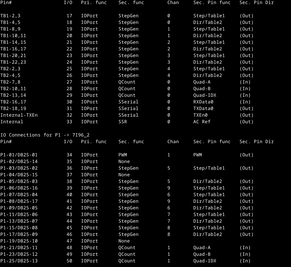
Looking at thr 5abob.pin file, that has 5 more stepgens (5 through to 9) on the P1 connector.
Looking at thr 5abob.pin file, that has 5 more stepgens (5 through to 9) on the P1 connector.
IO Connections for TB3 -> 7I96_0
Pin# I/O Pri. func Sec. func Chan Sec. Pin func Sec. Pin Dir

TB3-1 0 IOPort InM 0 Input0 (In)
TB3-2 1 IOPort InM 0 Input1 (In)
TB3-3 2 IOPort InM 0 Input2 (In)
TB3-4 3 IOPort InM 0 Input3 (In)
TB3-5 4 IOPort InM 0 Input4 (In)
TB3-6 5 IOPort InM 0 Input5 (In)
TB3-7 6 IOPort InM 0 Input6 (In)
TB3-8 7 IOPort InM 0 Input7 (In)
TB3-9 8 IOPort InM 0 Input8 (In)
TB3-10 9 IOPort InM 0 Input9 (In)
TB3-11 10 IOPort InM 0 Input10 (In)
TB3-13,14 11 IOPort SSR 0 Out-00 (Out)
TB3-15,16 12 IOPort SSR 0 Out-01 (Out)
TB3-17,18 13 IOPort SSR 0 Out-02 (Out)
TB3-19,20 14 IOPort SSR 0 Out-03 (Out)
TB3-21,22 15 IOPort OutM 0 Output4 (Out)
TB3-23,24 16 IOPort OutM 0 Output5 (Out)

IO Connections for TB1/TB2 -> 7I96_1
Pin# I/O Pri. func Sec. func Chan Sec. Pin func Sec. Pin Dir

TB1-2,3 17 IOPort StepGen 0 Step/Table1 (Out)
TB1-4,5 18 IOPort StepGen 0 Dir/Table2 (Out)
TB1-8,9 19 IOPort StepGen 1 Step/Table1 (Out)
TB1-10,11 20 IOPort StepGen 1 Dir/Table2 (Out)
TB1-14,15 21 IOPort StepGen 2 Step/Table1 (Out)
TB1-16,17 22 IOPort StepGen 2 Dir/Table2 (Out)
TB1-20,21 23 IOPort StepGen 3 Step/Table1 (Out)
TB1-22,23 24 IOPort StepGen 3 Dir/Table2 (Out)
TB2-2,3 25 IOPort StepGen 4 Step/Table1 (Out)
TB2-4,5 26 IOPort StepGen 4 Dir/Table2 (Out)
TB2-7,8 27 IOPort QCount 0 Quad-A (In)
TB2-10,11 28 IOPort QCount 0 Quad-B (In)
TB2-13,14 29 IOPort QCount 0 Quad-IDX (In)
TB2-16,17 30 IOPort SSerial 0 RXData0 (In)
TB2-18,19 31 IOPort SSerial 0 TXData0 (Out)
Internal-TXEn 32 IOPort SSerial 0 TXEn0 (Out)
Internal 33 IOPort SSR 0 AC Ref (Out)

IO Connections for P1 -> 5ABOB
Pin# I/O Pri. func Sec. func Chan Sec. Pin func Sec. Pin Dir

Spindle-PWM 34 IOPort PWM 1 PWM (Out)
Drive-Enable 35 IOPort None
X-Step 36 IOPort StepGen 5 Step/Table1 (Out)
Input-P15 37 IOPort None
X-Dir 38 IOPort StepGen 5 Dir/Table2 (Out)
B-Step 39 IOPort StepGen 9 Step/Table1 (Out)
Y-Step 40 IOPort StepGen 6 Step/Table1 (Out)
B-Dir,Relay 41 IOPort StepGen 9 Dir/Table2 (Out)
Y-Dir 42 IOPort StepGen 6 Dir/Table2 (Out)
Z-Step 43 IOPort StepGen 7 Step/Table1 (Out)
Z-Dir 44 IOPort StepGen 7 Dir/Table2 (Out)
A-Step 45 IOPort StepGen 8 Step/Table1 (Out)
A-Dir 46 IOPort StepGen 8 Dir/Table2 (Out)
Input-P10 47 IOPort None
Input-P11 48 IOPort QCount 1 Quad-A (In)
Input-P12 49 IOPort QCount 1 Quad-B (In)
Input-P13 50 IOPort QCount 1 Quad-IDX (In)
Last edit: 05 Dec 2023 15:19 by andypugh.
Please Log in or Create an account to join the conversation.
- Bl484
- Offline
- Junior Member
-
Less
More
- Posts: 21
- Thank you received: 0
06 Dec 2023 08:35 #287339
by Bl484
Replied by Bl484 on topic P1 expansion port
Thanks, Andy, for your response.
I added the firmware you suggested.
How can I activate the new step generator that was added? I apologize if my question seems silly.
Attachments:
Please Log in or Create an account to join the conversation.
- tommylight
-

- Away
- Moderator
-
Less
More
- Posts: 21767
- Thank you received: 7440
06 Dec 2023 10:08 #287343
by tommylight
Replied by tommylight on topic P1 expansion port
In the hal file, loadrt line containing stepgens, add more stepgens.
Please Log in or Create an account to join the conversation.
- Bl484
- Offline
- Junior Member
-
Less
More
- Posts: 21
- Thank you received: 0
06 Dec 2023 21:21 - 06 Dec 2023 22:39 #287389
by Bl484
Replied by Bl484 on topic P1 expansion port
Thank you for your support.
As I understand it, the new firmware adds 5 additional step generators. In the previous configuration, the 5-step generator sent signals to IO-port numbers 17, 19, 21, 23, 25. With the new firmware, the five new step generators send signals to IO-port numbers 36, 39, 40, 43, 45.
When using the Gcode command "G1 X10," the signal is sent to IO17. However, I would like to direct the signal to the P1 expansion port, for example, IO36.
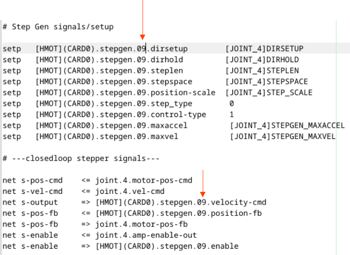
I attempted to resolve my issue by adjusting the step generator's number in the Hal file. As indicated in the attached file, I modified the step generator's number from 04 to 09, anticipating the signal on pin IO39 and IO41 instead of IO25 and IO26. However, regrettably, I cannot detect any voltage change in the newly assigned pins. .
How can I achieve this? (This was my initial question.)
Additionally, I am now curious to know how to command the extra step generators created by this new firmware.
As I understand it, the new firmware adds 5 additional step generators. In the previous configuration, the 5-step generator sent signals to IO-port numbers 17, 19, 21, 23, 25. With the new firmware, the five new step generators send signals to IO-port numbers 36, 39, 40, 43, 45.
When using the Gcode command "G1 X10," the signal is sent to IO17. However, I would like to direct the signal to the P1 expansion port, for example, IO36.
I attempted to resolve my issue by adjusting the step generator's number in the Hal file. As indicated in the attached file, I modified the step generator's number from 04 to 09, anticipating the signal on pin IO39 and IO41 instead of IO25 and IO26. However, regrettably, I cannot detect any voltage change in the newly assigned pins. .
How can I achieve this? (This was my initial question.)
Additionally, I am now curious to know how to command the extra step generators created by this new firmware.
Attachments:
Last edit: 06 Dec 2023 22:39 by Bl484.
Please Log in or Create an account to join the conversation.
- PCW
-
- Away
- Moderator
-
Less
More
- Posts: 17997
- Thank you received: 5284
06 Dec 2023 22:40 #287391
by PCW
Replied by PCW on topic P1 expansion port
Assuming you are not using stepgen 0..4, you would need to edit the hal file so
it refers to stepgens 5..8 rather than stepgens 0..4
Which brings up the question: Why are you not using the 7I96S TB1,TB2 stepgen outputs?
These are buffered 5V signals intended connect directly to motor drives.
The P1 signals are unbuffered 3.3V signals
it refers to stepgens 5..8 rather than stepgens 0..4
Which brings up the question: Why are you not using the 7I96S TB1,TB2 stepgen outputs?
These are buffered 5V signals intended connect directly to motor drives.
The P1 signals are unbuffered 3.3V signals
Please Log in or Create an account to join the conversation.
- Bl484
- Offline
- Junior Member
-
Less
More
- Posts: 21
- Thank you received: 0
06 Dec 2023 23:01 - 06 Dec 2023 23:27 #287392
by Bl484
Replied by Bl484 on topic P1 expansion port
I aimed to streamline my wiring setup by using a 26-pin IDC Flat Rainbow cable. Consequently, I opted to utilize the P1 expansion port in lieu of TB1 and TB2. ")
Please advise me on whether this is feasible or not.
Additionally, could you specify which Hal file you are referring to? As I mentioned earlier, I altered the step generator number in my Hal file (my_machine.hal). However, I couldn't observe any voltage changes on the pins.
Please advise me on whether this is feasible or not.
Additionally, could you specify which Hal file you are referring to? As I mentioned earlier, I altered the step generator number in my Hal file (my_machine.hal). However, I couldn't observe any voltage changes on the pins.
Last edit: 06 Dec 2023 23:27 by Bl484.
Please Log in or Create an account to join the conversation.
- PCW
-
- Away
- Moderator
-
Less
More
- Posts: 17997
- Thank you received: 5284
06 Dec 2023 23:50 #287393
by PCW
Replied by PCW on topic P1 expansion port
Are you buffering the step/dir signals from P1?
As I said, these are 3.3V signals.
You would need to change all the stepgen numbers
for this to work (including all the setup "setp"s)
As I said, these are 3.3V signals.
You would need to change all the stepgen numbers
for this to work (including all the setup "setp"s)
Please Log in or Create an account to join the conversation.
Time to create page: 0.186 seconds