Multiple Z axis XYZVW - gremlin display and control
- cncrcelec
- Offline
- New Member
-

Less
More
- Posts: 4
- Thank you received: 2
03 Feb 2024 22:13 #292336
by cncrcelec
Multiple Z axis XYZVW - gremlin display and control was created by cncrcelec
How can I set up 3 x Z axis' in LinuxCNC?
I'm in the process of upgrading from one spindle to two spindles plus a laser all on separate Z axis' (3 x Z axis' in total: X, V and W) attached to the common Y axis fixed gantry. The workpiece moves along the X axis. I intend to use the primary X axis spindle for routing, the V axis laser for engraving and marking with a 5500mW laser and the W axis spindle for drilling.
I've got LinuxCNC configured and working with the 3 x Z axis' (ZVW). Initially the gremlin (I think it's called) preview in the Axis GUI moved the Y position when I moved the V axis and the Z axis when I moved the W axis. I found I can disable the movements for V and W by using the following in the INI file (although it does give the following on startup: "Warning: duplicate chars in geometry: ZZZYX"):
So, here are some questions:
1. Can I have Axis Gremlin GUI move Z axis when V moves?
2. Is it possible to have the Axis GUI preview show me the position of the separate spindles and laser? ie. Can I have 3 cones on the display?
3. Is it possible to use canned drilling cycles (eg. G83) that operate on the W axis instead of the Z axis?
4. Can I use the tooltable offsets to define the offsets between my 3 x Z axis'?
5. Am I completely off track - is there a better way to configure this machine than to use XYZVW?
Askjerry has an interesting video on using custom M codes to change between spindle and laser () but I'm hoping the tooltable offsets will achieve the same result for me.
Any ideas welcome!
Thanks, David
I'm in the process of upgrading from one spindle to two spindles plus a laser all on separate Z axis' (3 x Z axis' in total: X, V and W) attached to the common Y axis fixed gantry. The workpiece moves along the X axis. I intend to use the primary X axis spindle for routing, the V axis laser for engraving and marking with a 5500mW laser and the W axis spindle for drilling.
I've got LinuxCNC configured and working with the 3 x Z axis' (ZVW). Initially the gremlin (I think it's called) preview in the Axis GUI moved the Y position when I moved the V axis and the Z axis when I moved the W axis. I found I can disable the movements for V and W by using the following in the INI file (although it does give the following on startup: "Warning: duplicate chars in geometry: ZZZYX"):
[DISPLAY]
GEOMETRY = XYZZZ
So, here are some questions:
1. Can I have Axis Gremlin GUI move Z axis when V moves?
2. Is it possible to have the Axis GUI preview show me the position of the separate spindles and laser? ie. Can I have 3 cones on the display?
3. Is it possible to use canned drilling cycles (eg. G83) that operate on the W axis instead of the Z axis?
4. Can I use the tooltable offsets to define the offsets between my 3 x Z axis'?
5. Am I completely off track - is there a better way to configure this machine than to use XYZVW?
Askjerry has an interesting video on using custom M codes to change between spindle and laser () but I'm hoping the tooltable offsets will achieve the same result for me.
Any ideas welcome!
Thanks, David
Please Log in or Create an account to join the conversation.
- Aciera
-

- Offline
- Administrator
-

Less
More
- Posts: 4766
- Thank you received: 2138
04 Feb 2024 08:58 #292362
by Aciera
Replied by Aciera on topic Multiple Z axis XYZVW - gremlin display and control
Removing the unwanted axis letters from the GEOMETRY entry in the ini should be enough to keep the cone from moving:
[DISPLAY]
GEOMETRY = XYZ
The answer to questions 1 and 2 would depend on your ability to modify 'glcanon.py'. Certainly possible but no easy solution.
3. No
4. Yes
5. Not 'completely off track' but there may be alternatives to using V and W axes. If you are using different joints for the spindles you might be better off using a custom kinematic and switch between the different axis-joint mappings. This way all your gcode could be kept in XYZ.
I'm sure there are other opinions on this so maybe wait a bit for others to join the discussion.
The following user(s) said Thank You: cncrcelec
Please Log in or Create an account to join the conversation.
- tommylight
-

- Away
- Moderator
-

Less
More
- Posts: 21764
- Thank you received: 7438
04 Feb 2024 13:29 #292378
by tommylight
Replied by tommylight on topic Multiple Z axis XYZVW - gremlin display and control
I think Todd has some machines using more than one Z axis, but he is absent lately.
Try serching the forum for his username, but be warned, he helps a lot so a lot to sift through.
Sorry, on the phone so i can not use google fu.
Try serching the forum for his username, but be warned, he helps a lot so a lot to sift through.
Sorry, on the phone so i can not use google fu.
The following user(s) said Thank You: cncrcelec
Please Log in or Create an account to join the conversation.
- cncrcelec
- Offline
- New Member
-
Less
More
- Posts: 4
- Thank you received: 2
08 Feb 2024 05:55 #292823
by cncrcelec
Replied by cncrcelec on topic Multiple Z axis XYZVW - gremlin display and control
Thanks for the suggestions ")
I've now got the machine running with the the 3 x Z axes: main spindle, laser engraver and drilling spindle on ZVW respectively. The concept of a custom kinematic is intriguing. Would you set up 3 joints and link them all to the one "Z" axis but only operate the 'active' joint based on a state stored in the kinematic component? Does Axis still think it only has one 'Z' axis but perhaps swap between the joints with a HAL 'variable' or something? Perhaps use some custom M codes to change the active axis? Sorry, I'm not very experienced with LinuxCNC - still trying to piece it all together. Maybe I'm off track.
I found these useful pages:
linuxcnc.org/docs/html/man/man9/userkins.9.html
raw.githubusercontent.com/LinuxCNC/linux...onents/userkins.comp
The 'GEOMETRY = XYZ' option works well, but I obviously don't get preview of V and W movements in the Axis GUI. No problem for the laser as it stays at the same V height but it would be nice to see the drilling in the preview.
The tool offsets work perfectly now that I've realized you need to do a G43 following the tool change to load the offset. Here is the boilerplate code I'm using:
[/code]
I've encountered some issues with retraction on the W axis - the X axis starts moving before the W axis has retracted from the hole it's drilling. I've submitted another post about that here .
I really appreciate the assistance, David
I've now got the machine running with the the 3 x Z axes: main spindle, laser engraver and drilling spindle on ZVW respectively. The concept of a custom kinematic is intriguing. Would you set up 3 joints and link them all to the one "Z" axis but only operate the 'active' joint based on a state stored in the kinematic component? Does Axis still think it only has one 'Z' axis but perhaps swap between the joints with a HAL 'variable' or something? Perhaps use some custom M codes to change the active axis? Sorry, I'm not very experienced with LinuxCNC - still trying to piece it all together. Maybe I'm off track.
I found these useful pages:
linuxcnc.org/docs/html/man/man9/userkins.9.html
raw.githubusercontent.com/LinuxCNC/linux...onents/userkins.comp
The 'GEOMETRY = XYZ' option works well, but I obviously don't get preview of V and W movements in the Axis GUI. No problem for the laser as it stays at the same V height but it would be nice to see the drilling in the preview.
The tool offsets work perfectly now that I've realized you need to do a G43 following the tool change to load the offset. Here is the boilerplate code I'm using:
[code]M6 T102 ; Change to tool 5mm dia drill (secondary DC spindle)
G43 ; Apply tool offsets
<drilling here>
M6 T101 ; Change to tool laser (5500mW diode laser)
G43 ; Apply tool offsetsM64 P0 ; turn on laser
<laser engraving here>M65 P0 ; turn off laserM6 T100 ; Change to tool 6mm dia end mill (main 2.2kW spindle)
G43 ; Apply tool offsets
<routing here>
I've encountered some issues with retraction on the W axis - the X axis starts moving before the W axis has retracted from the hole it's drilling. I've submitted another post about that here .
I really appreciate the assistance, David
Please Log in or Create an account to join the conversation.
- Aciera
-
- Offline
- Administrator
-
Less
More
- Posts: 4766
- Thank you received: 2138
08 Feb 2024 14:00 - 04 Jan 2025 10:45 #292847
by Aciera
That is pretty much spot on.
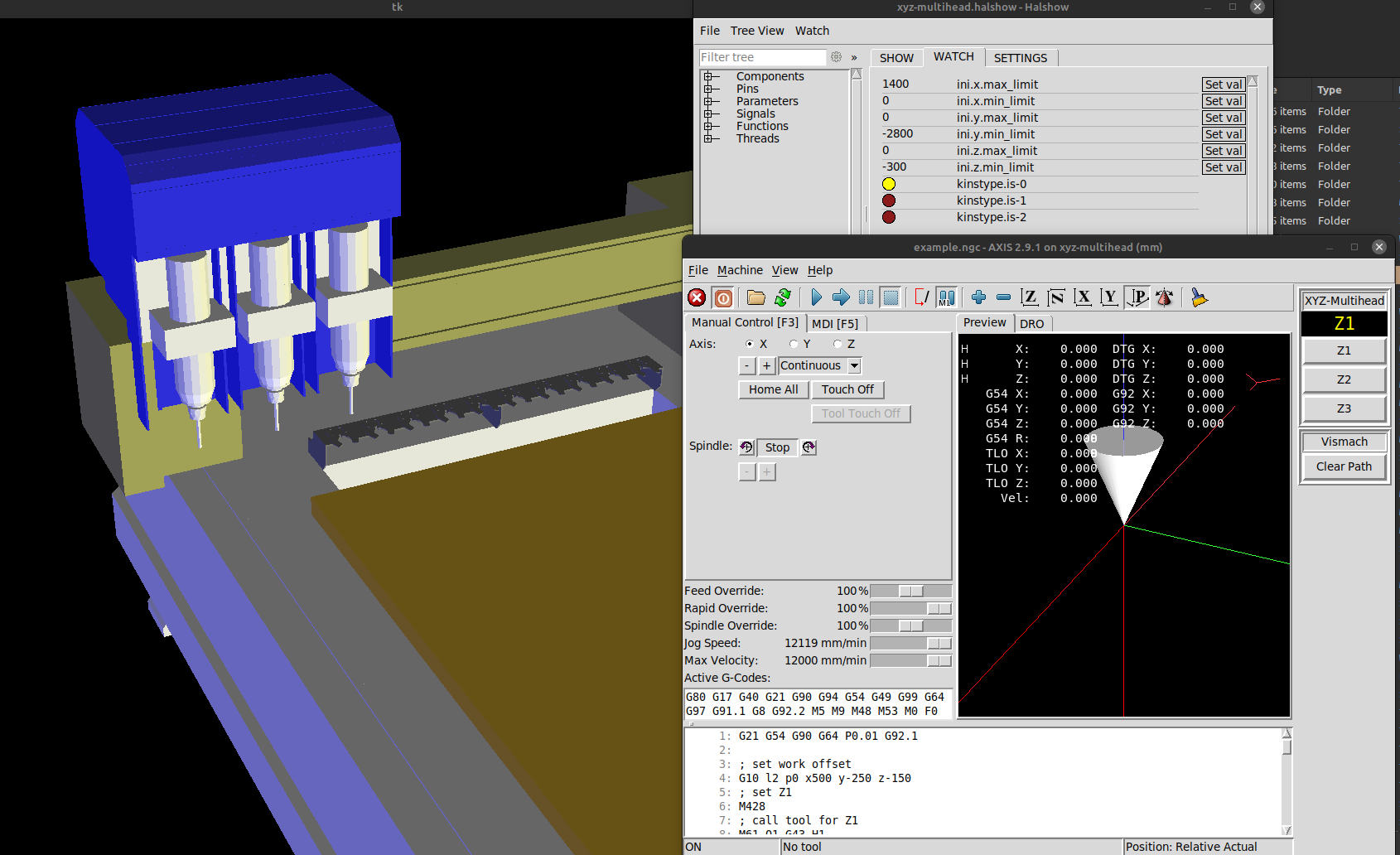
I have created a sim config for an XYZ gantry machine with 3 heads:
github.com/Sigma1912/LinuxCNC_Demo_Confi...e/main/xyz-multihead
To test you need to install the custom component 'xyz_multihead.comp'. Instructions can be found in the enclosed README.
Replied by Aciera on topic Multiple Z axis XYZVW - gremlin display and control
Would you set up 3 joints and link them all to the one "Z" axis but only operate the 'active' joint based on a state stored in the kinematic component? Does Axis still think it only has one 'Z' axis but perhaps swap between the joints with a HAL 'variable' or something? Perhaps use some custom M codes to change the active axis?
That is pretty much spot on.
I have created a sim config for an XYZ gantry machine with 3 heads:
github.com/Sigma1912/LinuxCNC_Demo_Confi...e/main/xyz-multihead
To test you need to install the custom component 'xyz_multihead.comp'. Instructions can be found in the enclosed README.
Attachments:
Last edit: 04 Jan 2025 10:45 by Aciera. Reason: Replace zipped config folder with link to github repo
Please Log in or Create an account to join the conversation.
- Aciera
-
- Offline
- Administrator
-
Less
More
- Posts: 4766
- Thank you received: 2138
08 Feb 2024 14:13 #292849
by Aciera
Replied by Aciera on topic Multiple Z axis XYZVW - gremlin display and control
Note that you could also handle the spindle offsets using an automatic shift in the current work offset when changing the kinematic. Or possibly automatic adjustment of the current tool offset values.
As mentioned in the README you can automatically change z-axis settings from the ini file (currently commented out in the M428, M429, M430 remaps). Ie you could adjust the acceleration, velocity, and limit values for the z-axis depending on the head currently selected.
Switchable kinematics has been merged into Linuxcnc rather recently so not many users have made use of it outside of 5-axis configurations or robots. Personally I find that it's capabilities are very much underrated and many potential uses are still to be discovered.
The following user(s) said Thank You: tommylight
Please Log in or Create an account to join the conversation.
Time to create page: 0.135 seconds